
This blog is to provide the guideline how to set up the nRF9160 DK board and connect to the nRF Cloud.
It would cover the following topic.
- Select the modem firmware and program
- Register nRF91 DK to the nRF Cloud
- Running few examples such as Asset Tracker, COAP Client, AT Client.
When you get the nRF9160 DK board, you should need to backup the firmware and key from the board.
If you carelessly erase the entire flash inside the nRF91, you would lose the key that cause failure to link to the network.
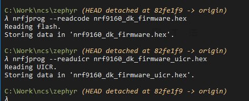
Caution ! Please don’t erase the entire flash of the chip.
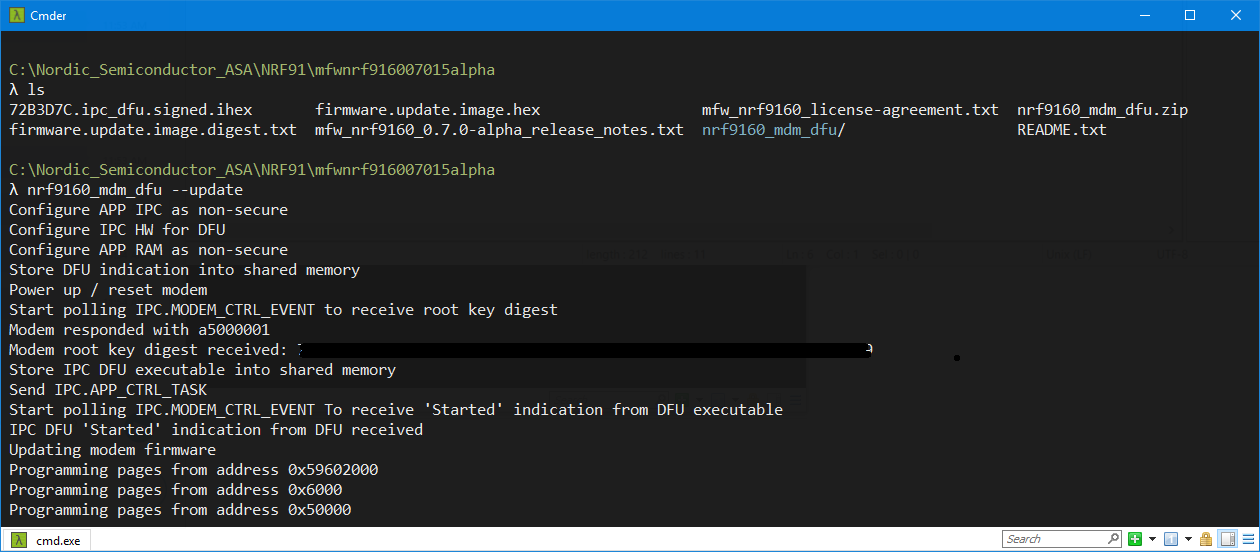
Modem firmware
- Select the right modem firmware from Nordic Web page. [Link]

nRF9160 DK board controller firmware
This is the FW of the nRF52840 at the nRF9160 DK board. The default nRF52840 chipset is used to control the GPIO at the nRF91 DK board.
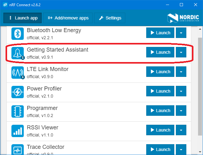
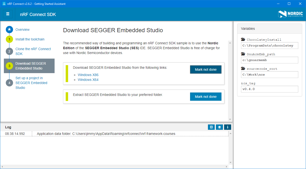
Installation of the NCS (nRF Connect SDK)
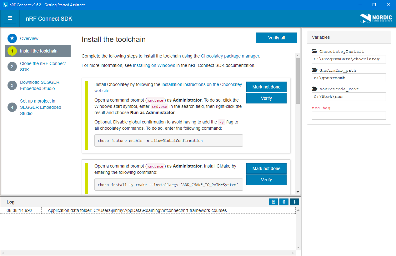
For the installation guide, you can refer to the “Getting Started Assistant” inside the nRF Connect APP.
Install the Toolchain
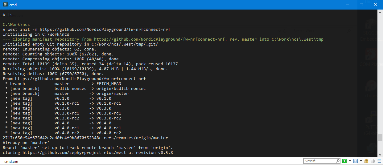
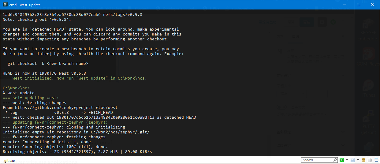
Getting the NCS from Git through West
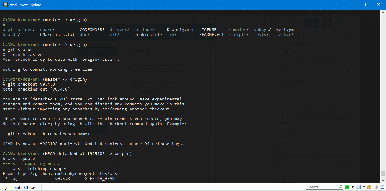
Check the version of the NCS
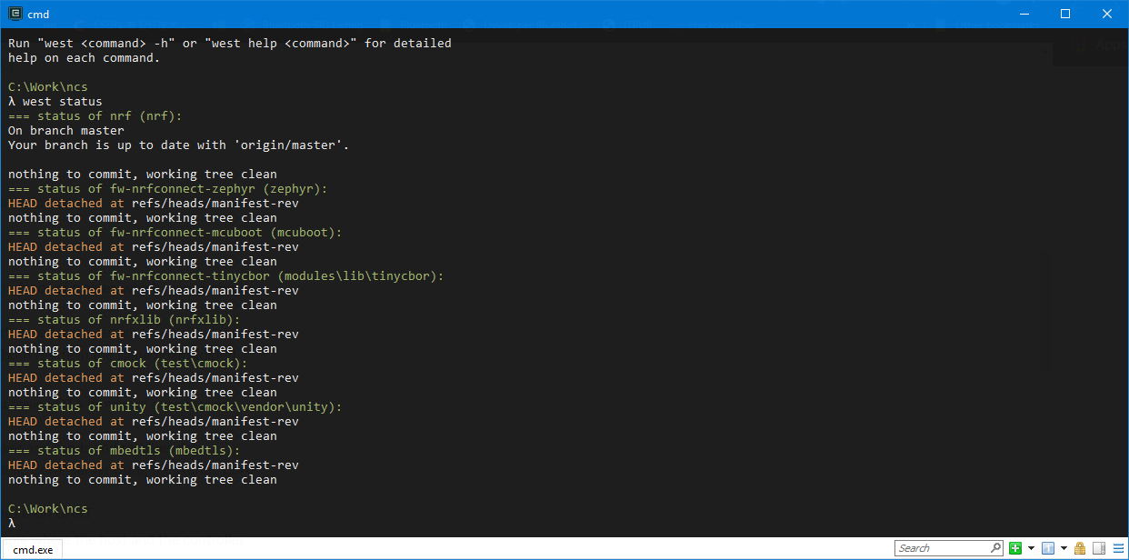
Currently (14th May, 2019), the latest tag of the NCS is v0.4.0.
https://developer.nordicsemi.com/nRF_Connect_SDK/doc/0.4.0/nrf/index.html
This project is hosted by Nordic Semiconductor to demonstrate the integration of Nordic SoC support in open source projects, like MCUBoot and the Zephyr RTOS, with libraries and source code for low-power wireless applications.
nRF Connect SDK v0.4.0 supports development with nRF9160 Cellular IoT devices. It contains references and code for Bluetooth Low Energy devices in the nRF52 Series, though development on these devices is not currently supported with the nRF Connect SDK.
Release Note (NCS) of v0.4.0
https://developer.nordicsemi.com/nRF_Connect_SDK/doc/0.4.0/nrf/doc/release-notes-0.4.0.html
nRF9160
- Deprecated the
nrf91branch in fw-nrfconnect-zephyr in favor of master, which now supports the nRF9160 IC - Split the previous
nrf9160_pca10090board into two boards, one for the secure (nrf9160_pca10090) and one for the non-secure (nrf9160_pca10090ns) image (both reside in the same board folder) - Added the following samples:
- nRF9160: HTTP application update – demonstrates a basic FOTA (firmware over-the-air) update using the Download client
- nRF9160: Simple MQTT – connects to an MQTT broker and sends and receives data
- nRF9160: nRF CoAP Client – receives data from a public CoAP server using the Nordic CoAP library
- Simple GPS sample – gets the current position and logs it on UART
- Fixed an issue in the nRF9160: LTE Sensor Gateway sample where the host and the controller would go out of sync after a reset
- Various fixes and updates to BSD Library, sockets offloading layer, and OS adaption:
- Updated the BSD Library (in nrfxlib) library to version 0.3.0 (see the Changelog for details)
- Added support for GNSS supporting GPS as a socket (in nrfxlib)
- Implemented
bsd_os_timedwait()(inlib/bsdlib/bsd_os.cin fw-nrfconnect-nrf), allowing a proper poll operation and blocking sockets - Minor fixes to the nRF91 sockets offloading layer (in
lib/bsdlib/nrf91_sockets.cin fw-nrfconnect-nrf)
Checkout the version v0.4.0
Highlights
- Added support for the new triple mode (LTE-M/NB-IoT/GPS) with
mfw_nrf9160_0.7.0-29.alpha(see Network mode for instructions for changing the network mode) - Updated BSD library:
- Added API supporting GPS
- Fixed various issues (see the Changelog)
- Added sample showing how to use the new GPS API (tested on nRF9160 DK v0.8.5)
- Added sample showing how to download a new image via HTTP
- Added multi-image support (see Partition Manager)
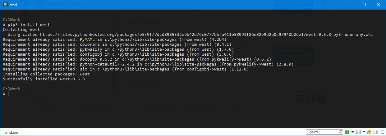
Install all the python necessary modules
cd <sourcecode_root>\ncs
pip3 install -r zephyr\scripts\requirements.txt
pip3 install -r nrf\scripts\requirements.txt
pip3 install -r mcuboot\scripts\requirements.txt
Required tools
In addition to the tools mentioned in Installing the nRF Connect SDK, the following tool versions are required to work with the nRF Connect SDK:
| Tool | Version | Download link |
|---|---|---|
| SEGGER J-Link | V6.41 | J-Link Software and Documentation Pack |
| nRF5x Command Line Tools | v9.8.1 | nRF5x Command Line Tools |
| dtc (Linux only) | v1.4.6 or later | Installing the required tools |
As IDE, we recommend to use SEGGER Embedded Studio (Nordic Edition), version 4.16 or later. It is available from the following links:
- SEGGER Embedded Studio (Nordic Edition) – Windows x86
- SEGGER Embedded Studio (Nordic Edition) – Windows x64
- SEGGER Embedded Studio (Nordic Edition) – Mac OS x64
- SEGGER Embedded Studio (Nordic Edition) – Linux x86
- SEGGER Embedded Studio (Nordic Edition) – Linux x64
Example I: Asset Tracker (v0.3.0)
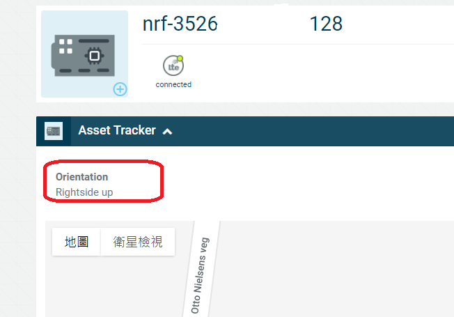
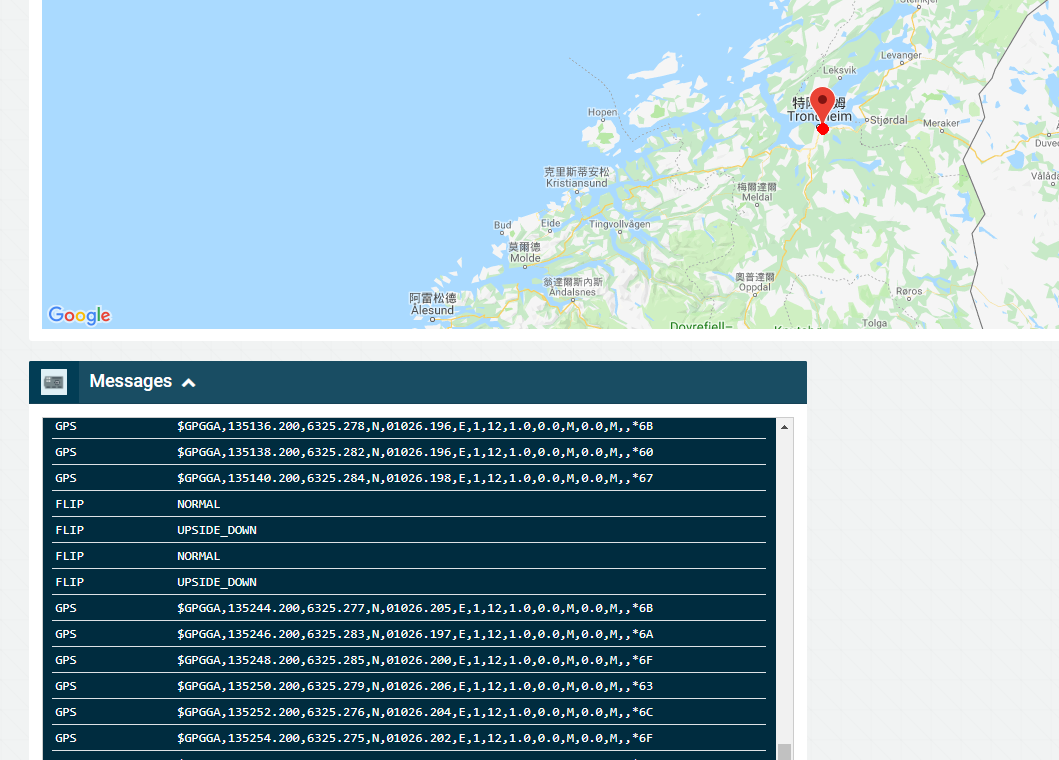
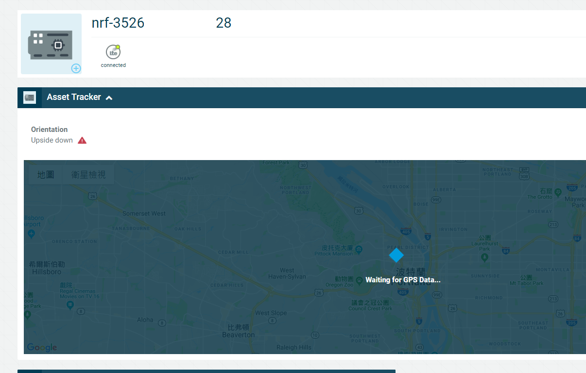
The sample sends GPS position data and accelerometer data that is collected by an nRF9160 DK to Nordic Semiconductor’s cloud solution, nRF Cloud, where the data is visualized.
The accelerometer data is used to infer the device’s physical orientation.
It is sent as the nRF Cloud sensor data type “FLIP”.
By default, the sample uses simulated sensor and GPS data.
The LTE link control driver is used to establish the LTE link automatically.
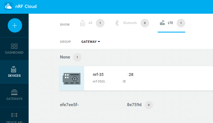
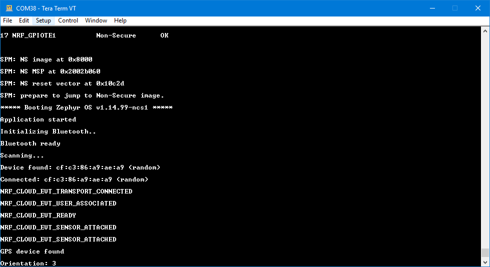
After running on the Asset Tracker firmware, the nRF91 DK would connect to the network (cloud) as below.
Description
The two buttons and two switches are used to enter a pairing pattern to associate a specific board with an nRF Cloud user account.
In addition, the two switches have the following function when the connection is established:
Switch 1:
* Toggle to simulate flipping of the boards orientation.
Switch 2:
* Set to N.C. to send simulated GPS data to the nRF Cloud once every 2 seconds.
The application state is indicated by the LEDs.
LED 3 and LED 4:
* LED 3 blinking: Connecting – The device is resolving DNS and connecting to the nRF Cloud.
* LED 3 and LED 4 blinking: Pairing started – The MQTT connection has been established and the pairing procedure towards nRF Cloud has been initiated.
* LED 3 ON and LED 4 blinking: Pattern entry – The user has started entering the pairing pattern.
* LED 4 blinking: Pattern sent – Pattern has been entered and sent to nRF Cloud for verification.
* LED 4 ON: Connected – The device is ready for sensor data transfer.
Button 1 : Rightside up / Downside down
Button 2: Turn on / off GPS
Example II : AT Client (v0.3.0)
The AT command API can also be exposed on one of the nRF91 serial interfaces by programming appropriate firmware in the application core. The nRF Connect SDK contains examples of such proxy firmware that can be run stand-alone or as part of other firmware functionality in the nRF91 application core. The stand-alone example is called at_client. This way, an external MCU or computer can get access to the modem API either exclusively or in addition to application firmware running on the nRF91 itself.
Online document: [Link]
Based on difference operators, it needs to add specify AT command on ncs\nrf\drivers\lte_link_control.
// China Mobile Operator
////////////////////////////////////////////////////////////////////////
       err = at_cmd(at_socket_fd, "AT%XEPCO=0", 10);
       if (err) {
                 close(at_socket_fd);
                 return err;
       }
///////////////////////////////////////////////////////////////////
/* AT%XEPCO = 0 ---------- switches extended PCO option usage off
PCO = Protocol Configuration Option configures MTUS, DNS servers */
// Hong Kong CSL 1010 Operator
/*
- Change to NB-IoT mode:
AT%XSYSTEMMODE=0,1,0,0
- Lock B3 (optional):
AT%XBANDLOCK=2,"00000100"
- Lock CSL (optional):
AT+COPS=1,2,"45400"
- Set APN and get IPv4 address by DHCP (mandatory):
AT+CGDCONT=0,"IP","nbiotdirect",,,,1
*/By using the nRF Link Monitor, it can try the AT command for config.
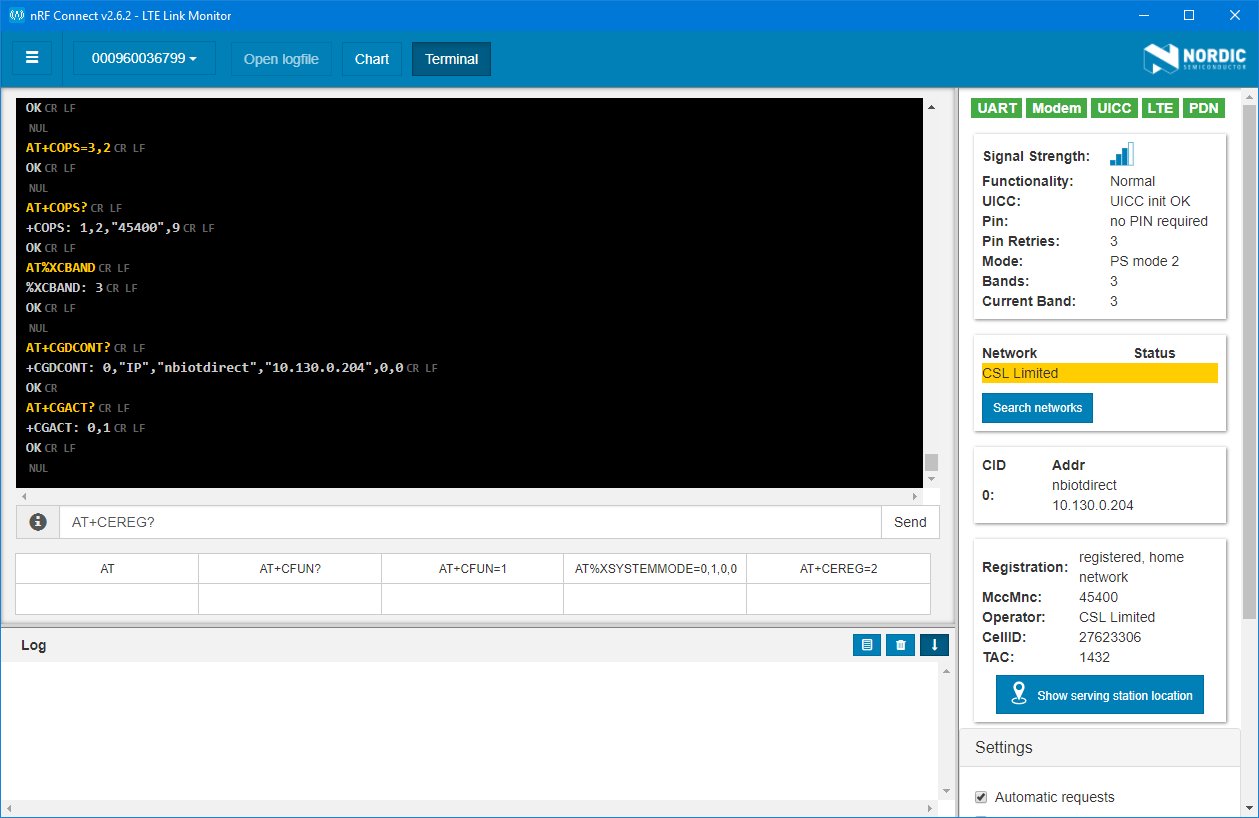
Some important AT commands:
- AT+CEREG? — The example command reads the current registration status
- AT+CFUN? — The +CFUN command sets and reads the modem functional mode
Example III : COAP Client (v0.4.0)
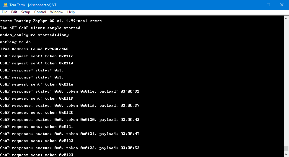
The nRF CoAP Client sample demonstrates how to receive data from a public CoAP server with an nRF9160 SiP.
Overview
The sample connects to a public CoAP test server, sends periodic GET request for a test resource that is available on the server, and prints the data that is received.
Testing
After programming the sample and all prerequisites to the board, test it by performing the following steps:
- Connect the USB cable and power on or reset your nRF9160 DK.
- Open a terminal emulator and observe that the kit prints the following information:The nRF CoAP client sample started
- Observe that the kit sends periodic CoAP GET requests after it gets LTE connection. The kit sends requests to the configured server (
CONFIG_COAP_SERVER_HOSTNAME) for a configured resource (CONFIG_COAP_RESOURCE). - Observe that the kit either prints the reponse data received from the server or indicates a time-out.
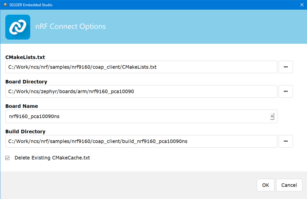
Step 1: Select the correct path as below
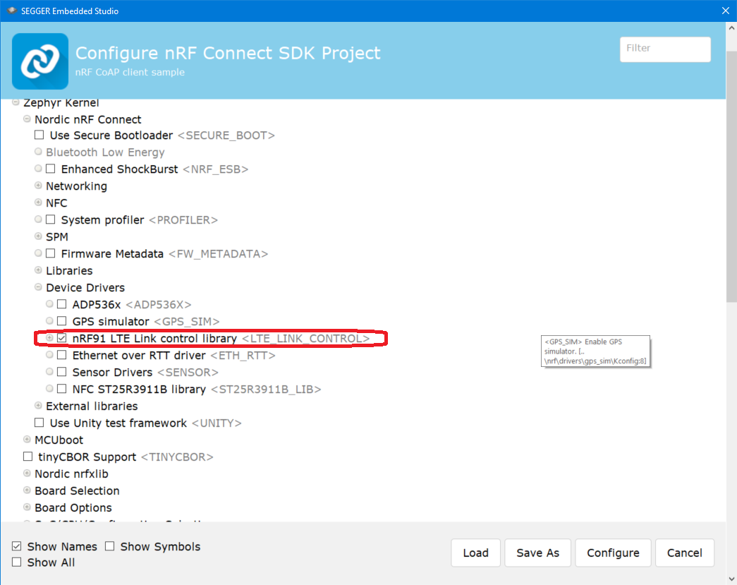
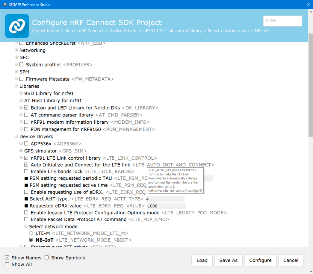
Step 2: Configure the NRF91 LTE Link control
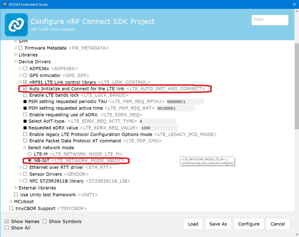
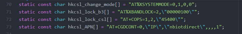
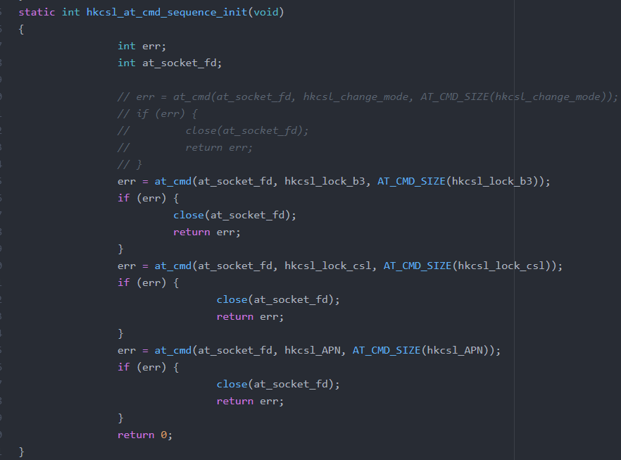
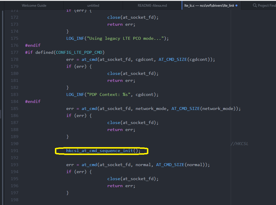
Step 3: By using the HK CSL (1010) operator, it supports only NBIOT and APN configuration as below. (ncs\nrf\drivers\lte_link_control\lte_lc.c)
Step 4: Program the hex through Segger Embedded Studio
Note:
There is currently a bug in SES (Segger Embedded Studio) where it does not choose the ../<project>/<build_folder>/zephyr/merged.hex, where it instead takes the zephyr.hex in the same folder.
To make this work, you need to manually flash the merged.hex initially, then you can flash from SES afterwards.
Example IV: LTE Sensor Gateway
The LTE Sensor Gateway sample demonstrates how to transmit sensor data from an nRF9160 DK to the nRF Cloud. Unlike the nRF9160: Asset Tracker sample, the sensor data is collected via Bluetooth LE. Therefore, this sample acts as a gateway between Bluetooth LE and the LTE connection to the nRF Cloud.
Overview
The sample connects via Bluetooth LE to a Thingy:52 that is running the factory pre-loaded application. It then starts collecting data from two sensors:
- The flip state of the Thingy:52
- Simulated GPS position data
The data from both sensors is aggregated in memory. Flipping the Thingy:52, which causes a change in the flip state to “UPSIDE_DOWN”, triggers an alarm that sends the aggregated data over LTE to the nRF Cloud.
Requirements
- A Nordic Thingy:52
- The following development board:
- nRF9160 DK board (PCA10090)
- Bluetooth: HCI UART must be programmed to the nRF52 board controller on the board.
- The sample is configured to compile and run as a non-secure application on nRF91’s Cortex-M33. Therefore, it automatically includes the nRF9160: Secure Partition Manager that prepares the required peripherals to be available for the application.
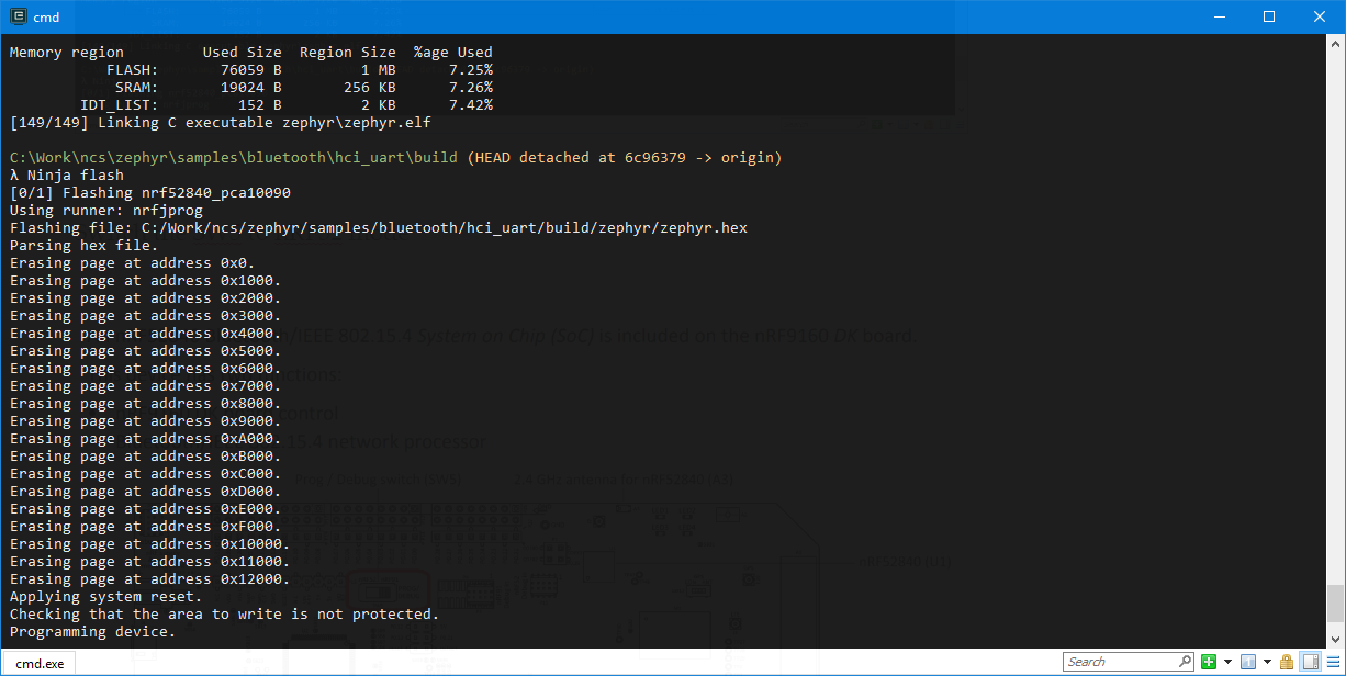
Prepare / Compile the hex on the nRF52840 (HCI UART)
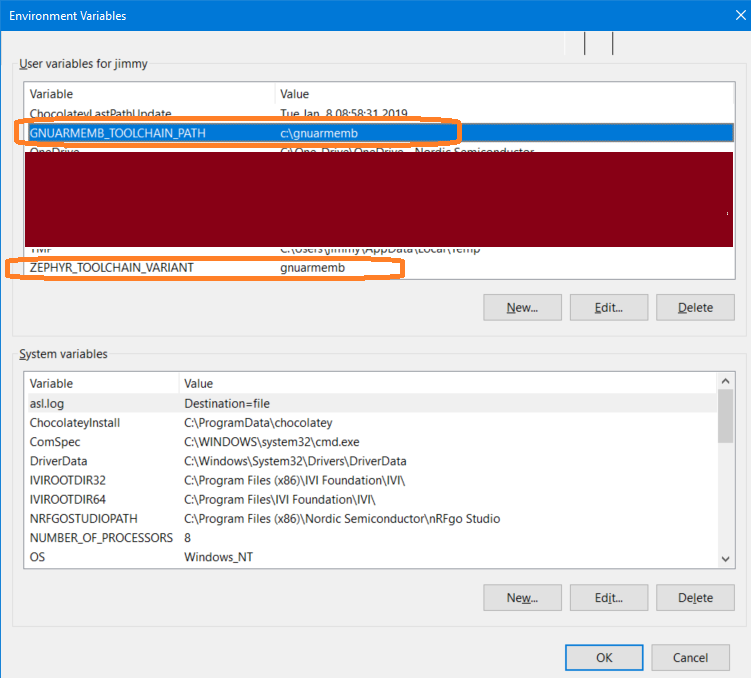
Step 1: Set the environment variables (GNUARMEMB_TOOLCHAIN_PATH and ZEPHYR_TOOLCHAIN_VARIANT)
Step 2: run the zephyr-env.cmd under the \ncs\zephyr
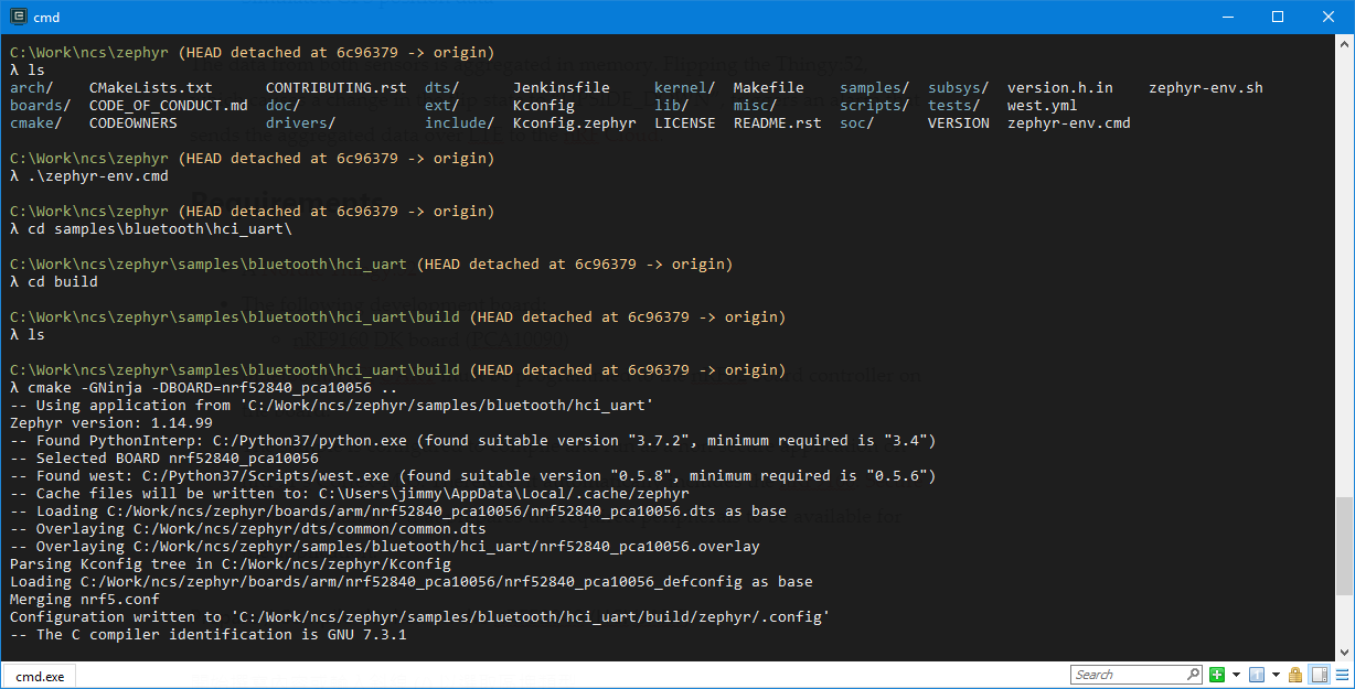
Step 3:
cd samples\bluetooth\hci_uart
mkdir build & cd build
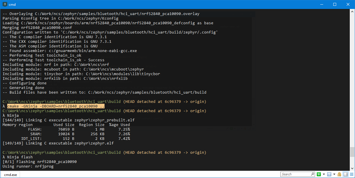
cmake -GNinja -DBOARD=nrf52840_pca10090 ..
NinjaStep 4: Program the HCI_UART hex on the nRF52840 chipset
Switch the SW5 to nRF52 mode
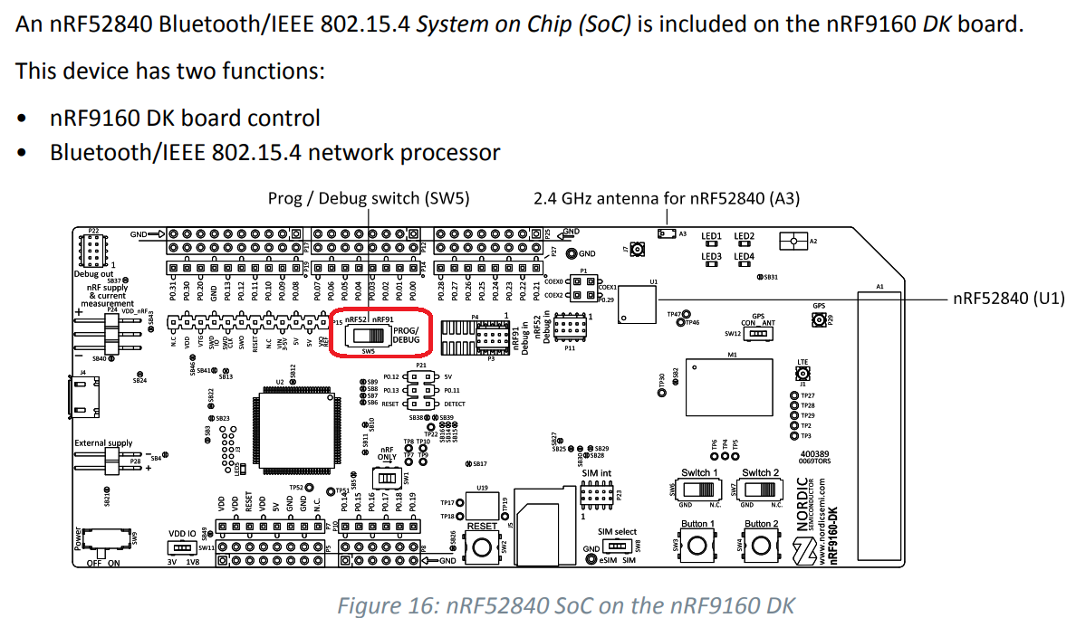
The precompiled hex of the nRF52840 on NRF9160 DK is here.
Prepare the hex for the LTE mode
Setup the project configuration for SES on lte_ble_gateway application
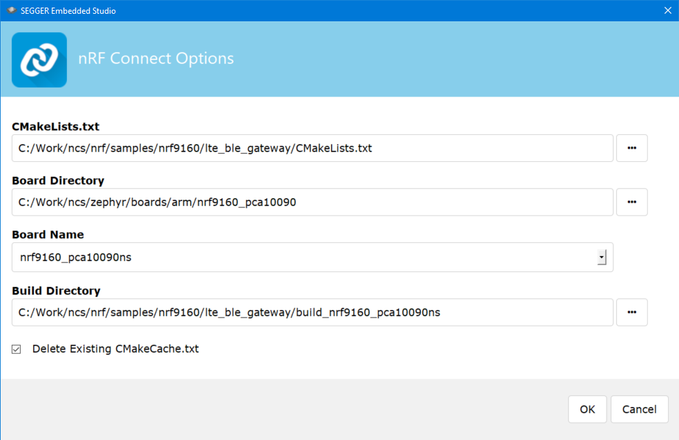
Configure the NBIOT mode (for HK CSL 1010 operator)
Result
We can check on the output log at the nRF9160 DK board.
With the nRF cloud, it shows that the nRF9160 DK board connects to cloud.

I may have deleted the key to connect to the network you mention in the first few paragraphs. How do I recover it?
LikeLike
You can login your nrfcloud account and fill up the hardware information on it.
If you still have the problem, I prefer to raise your question to ask through Nordic Devzone.
They would help you to solve the problem.
LikeLike