
In the embedded system, MCU may need to communicate with other devices such as sensors, PC host, and Bluetooth module. Most of the time, those devices cannot be directly connected to GPIO pins with MCU. It should go through a communication protocol in between MCU and devices. One of the most popular communication protocols should be the serial as well as UART. If you use the STM32 MCU, you can easier find out several web pages with example code how to build up the emulated UART on the STM32.
- Build an Interrupt-driven Software Serial for STM32F3 MCU
- Application Note: Implementing an emulated UAR on STM32F4 microcontrollers
In this blog, I would like to introduce how to build the software UART (emulator) based on the bit banging method. In the Nordic nRF52 series as below table, nRF52810, nRF52811 and nRF52832 have only 1 hardware UART peripheral. It may not be enough if you need to connect with 2 sensors through serial communication protocol.
| Chipset | Number of HW UART | Maximum length of UARTE DMA (bit) |
| NRF52810 | 1 | 10 (1024 bytes) |
| NRF52811 | 1 | 14 (4096 bytes) |
| NRF52832 | 1 | 8 (256 bytes) |
| NRF52833 | 2 | 16 (65536 bytes) |
| NRF52840 | 2 | 16 (65536 bytes) |
Fundamental of UART (refer to the URL)
By definition, UART is a hardware communication protocol that uses asynchronous serial communication with configurable speed. Asynchronous means there is no clock signal to synchronize the output bits from the transmitting device going to the receiving end.

Start Bit
The UART data transmission line is normally held at a high voltage level when it’s not transmitting data. To start the transfer of data, the transmitting UART pulls the transmission line from high to low for one (1) clock cycle. When the receiving UART detects the high to low voltage transition, it begins reading the bits in the data frame at the frequency of the baud rate.
Data Frame
The data frame contains the actual data being transferred. It can be five (5) bits up to eight (8) bits long if a parity bit is used. If no parity bit is used, the data frame can be nine (9) bits long. In most cases, the data is sent with the least significant bit first.
Parity
Parity describes the evenness or oddness of a number. The parity bit is a way for the receiving UART to tell if any data has changed during transmission. Bits can be changed by electromagnetic radiation, mismatched baud rates, or long-distance data transfers.
After the receiving UART reads the data frame, it counts the number of bits with a value of 1 and checks if the total is an even or odd number. If the parity bit is a 0 (even parity), the 1 or logic-high bit in the data frame should total to an even number. If the parity bit is a 1 (odd parity), the 1 bit or logic highs in the data frame should total to an odd number.
When the parity bit matches the data, the UART knows that the transmission was free of errors. But if the parity bit is a 0, and the total is odd, or the parity bit is a 1, and the total is even, the UART knows that bits in the data frame have changed.
Stop Bits
To signal the end of the data packet, the sending UART drives the data transmission line from a low voltage to a high voltage for one (1) to two (2) bit(s) duration.
Avoid software UART during BLE Radio Activity
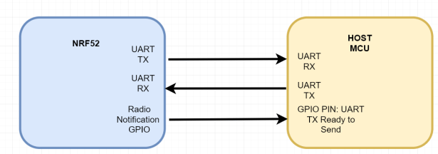
Since the BLE radio has the highest priority, the communicated protocol on the software UART should be avoided during the radio activity. The most straightforward approach is to use an additional handshaking gpio pin to indicate the external MCU about the status of the radio activity.
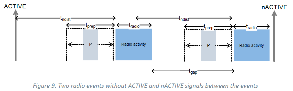
The INACTIVE notification is right after the radio goes inactive, regardless of the notification distance configured. In other words, the notification distance only applies to the ACTIVE signal, if enabled.
Note that the timings (ACTIVE notification distance, the phrase “right after the radio goes inactive”) refers to the instance where the software interrupt is set pending. The time you observe that the interrupt handler is executing may vary depending on the CPU activity at the different priority levels.
Tutorial how to use the radio notification
https://devzone.nordicsemi.com/tutorials/b/software-development-kit/posts/radio-notification
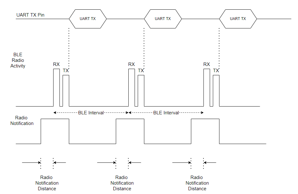
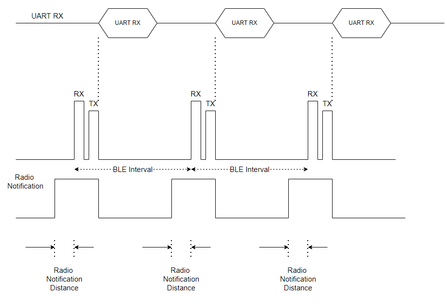
Both UART TX and RX as below figure are handled during the radio activity is inactive.
Software UART Transmission
Software UART Receive
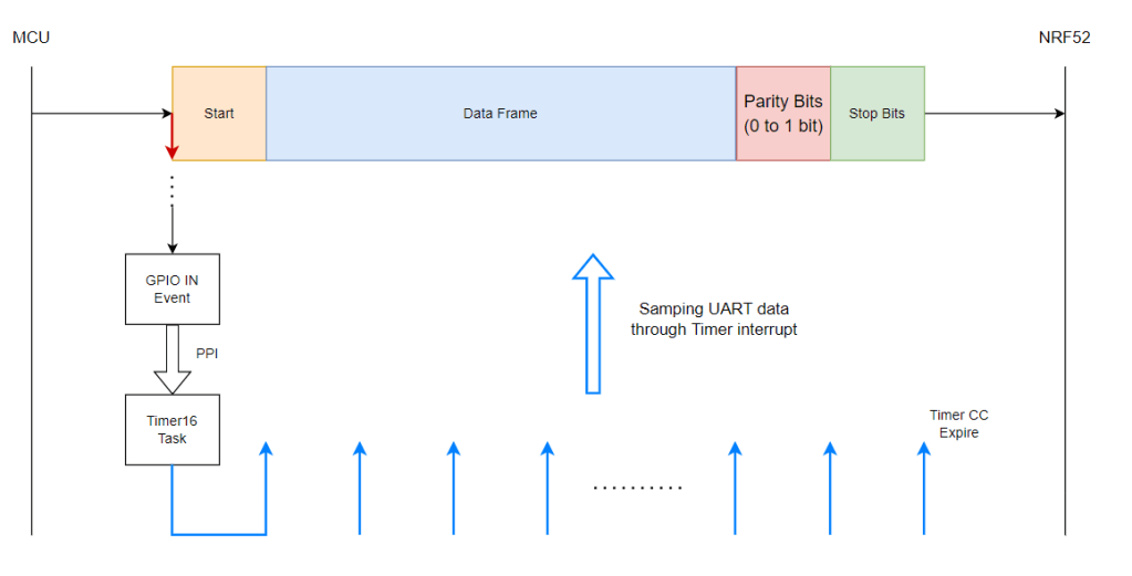
Block Diagram / Data flow on the Software UART RX
The key point is to trigger the fallen edge on the GPIO pin from high to low which indicates the first bit on the UART packet. By using the PPI, the Timer16 task is started by the GPIO IN event.
Enable the GPIO IN Event
ret_code = nrf_drv_gpiote_init();
APP_ERROR_CHECK(ret_code);

nrf_drv_gpiote_in_config_t rx_gpio_config = GPIOTE_CONFIG_IN_SENSE_HITOLO(true);
rx_gpio_config.pull = NRF_GPIO_PIN_PULLUP;
ret_code = nrf_drv_gpiote_in_init(m_rx_pin, &rx_gpio_config, rx_pin_handler);
APP_ERROR_CHECK(ret_code);

nrf_drv_gpiote_in_event_enable(m_rx_pin, true);
Enable the Timer16
ret_code = nrf_drv_timer_init(&TIMER_RX, &timer_cfg, rx_timer_handler);
APP_ERROR_CHECK(ret_code);
nrf_drv_timer_extended_compare(&TIMER_RX, NRF_TIMER_CC_CHANNEL0, m_bit_ticks, NRF_TIMER_SHORT_COMPARE0_STOP_MASK, true);
Enable the PPI to link between GPIO IN event and timer16 task
nrf_drv_ppi_channel_alloc(&rx_ppi);

evt_addr = nrf_drv_gpiote_in_event_addr_get(m_rx_pin);
task_addr = nrf_drv_timer_task_address_get(&TIMER_RX, NRF_TIMER_TASK_START);

nrf_drv_ppi_channel_assign(rx_ppi, evt_addr, task_addr);
nrf_drv_ppi_channel_enable(rx_ppi);
Block Diagram / Data flow on the Software UART TX
The method of the software UART TX is just to use the timer16 interrupt handler and feed the GPIO either high or low based on the transmission data.
nrf_drv_timer_config_t timer_cfg = NRF_DRV_TIMER_DEFAULT_CONFIG;
ret_code = nrf_drv_timer_init(&TIMER_TX, &timer_cfg, tx_timer_handler);
APP_ERROR_CHECK(ret_code);

nrf_drv_timer_enable(&TIMER_TX);

void tx_timer_handler(nrf_timer_event_t event_type, void* p_context)
{

    if (bit_counter  <  UART_DATA_LENGTH)
    {
        if (m_tx_data & (1 << bit_counter) == 1)
        {
            nrf_gpio_pin_set(m_tx_pin);
        }
        else
        {
            nrf_gpio_pin_clear(m_tx_pin);

        }
        bit_counter ++;
    }
...
}
Conclusion
Since the GPIO doesn’t support the direct memory access (DMA), the software UART can’t be supported up to 38400 baud rate. This limitation purely depends on the BLE radio activity. For the further improvement, the GPIO may be replaced by the peripheral with DMA such as SAADC (Successive approximation analog-to-digital converter).
Thank you for reading this post. Hope you learn the concept how to build up the software serial protocol after reading this post.
References
- “ Bit-banging ” retrieved from https://en.wikipedia.org/wiki/Bit_banging
- “ UART Communication : Block Diagram and Its Applications ” retrieved from https://www.elprocus.com/basics-of-uart-communication-block-diagram-applications/
- Application note, AN4655 — “ Virtually increasing the number of serial communication peripherals in STM32 applications ”
- Introduction to Bit Banging (Build an Interrupt-driven Software Serial for STM32F3 MCU)

Hi Jimmywong, first, thanks for the post.
I wonder if could you share the entire code on a repository, I will appreciate it because right now I’m facing with a similar issue like this.
Regards,
Fer Mercado.
LikeLike