This blog is to demo how to use the external SPI flash for Device Firmware Upgrade (DFU) on the nRF52 Series. The target is to minimize the size of the bootloader particular on the nRF52810. The total size of the bootloader + its setting is only 12KB comparing to original bootloader SDK (32KB).

Note: this example is only target to upgrade the application firmware.
In the Nordic SDK, it supports two difference DFU.
- Bootloader with BLE for Over the Air Upgrade
- Bootloader with Serial UART
Memory Layout
When adding a bootloader to your device, you must be aware of where in the device memory the different firmware components are located.
The following table shows the memory layout for the different chips with current SoftDevices:
| Usage | Memory range nRF52832 (S132 v6.1.x) | Memory range nRF52840 (S140 v6.1.x) | Memory range nRF52810 (S112 v6.1.x) |
|---|---|---|---|
| Bootloader settings | 0x0007 F000 – 0x0008 0000 (4 kB) | 0x000F F000 – 0x0010 0000 (4 kB) | 0x0002 F000 – 0x0003 0000 (4 kB) |
| MBR parameter storage | 0x0007 E000 – 0x0007 F000 (4 kB) | 0x000F E000 – 0x000F F000 (4 kB) | 0x0002 E000 – 0x0002 F000 (4 kB) |
| Bootloader | 0x0007 8000 – 0x0007 E000 (24 kB) | 0x000F 8000 – 0x000F E000 (24 kB) | 0x0002 8000 – 0x0002 E000 (24 kB) |
| Application area (incl. free space) | 0x0002 6000 – 0x0007 8000 (328 kB) | 0x0002 6000 – 0x000F 8000 (840 kB) | 0x0001 9000 – 0x0002 8000 (60 kB) |
| SoftDevice | 0x0000 1000 – 0x0002 6000 (148 kB) | 0x0000 1000 – 0x0002 6000 (148 kB) | 0x0000 1000 – 0x0001 9000 (96 kB) |
| Master Boot Record (MBR) | 0x0000 0000 – 0x0000 1000 (4 kB) | 0x0000 0000 – 0x0000 1000 (4 kB) | 0x0000 0000 – 0x0000 1000 (4 kB) |
The maximum size of the application layer is 60KB if using the nRF52810 with S112v6.1.x.
Proposal (External SPI Flash for DFU)
The size of the bootloader with SPI data flash (DFU) is reduced from 24KB to 8KB. Thus, the maximum size of application if using S112v5.1 can be increased up to 84KB.
If the device requires the pairing / bonding feature, it needs to reserve at least 2 extra pages for storing bonding information. The size of application region would be reduced to 84KB – 8KB (2 page) = 76KB.
| Usage | Memory range nRF52810 (S112 v5.1.x) | Memory range nRF52810 (S112 v6.1.x) |
| Bootloader settings | 0x0002 F000 – 0x0003 0000 (4 kB) | 0x0002 F000 – 0x0003 0000 (4 kB) |
| Bootloader | 0x0002 C000 – 0x0002 F000 (8 kB) | 0x0002 C000 – 0x0002 F000 (8 kB) |
| Application area (incl. free space) | 0x0001 8000 – 0x0002 C000 (84 kB) | 0x0001 9000 – 0x0002 C000 (80 kB) |
| SoftDevice | 0x0000 1000 – 0x0001 8000 (92 kB) | 0x0000 1000 – 0x0001 9000 (96 kB) |
| Master Boot Record (MBR) | 0x0000 0000 – 0x0000 1000 (4 kB) | 0x0000 0000 – 0x0000 1000 (4 kB) |
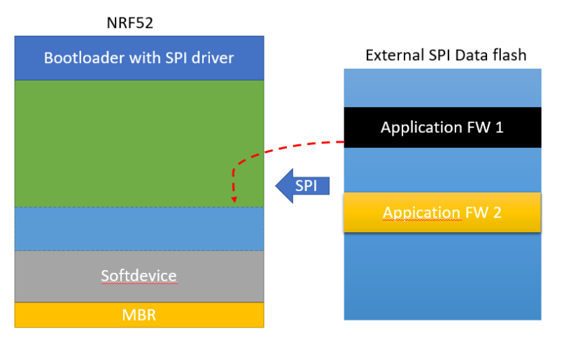
I use the NRF52840 DK board and configure the on-board QSPI to act as external SPI data flash in this demo.
In the example code, two individual application images are stored at the external SPI flash. The 2nd image is used as the default (backup) one. The bootloader would copy the default FW to the application region, if the application region is corrupted or blank (CRC check result is invalid). On the other hand, it would use the 1st FW for updating the application region.
Also, this example spi bootloader is independent from the SDK version. It means that it can work with difference Nordic SDK version.
Testing Procedure
Step 1
- Compile and link to 2 difference firmware hex file.
Step 2
- Modify the starting address of 2 difference firmware address on the SPI flash inside bootloader.
#define APP_CFG_INIT_START_ADDR  0x00000000

#define APP_CFG_FW_START_ADDR  0x00001000

define APP_CFG_INIT_START_ADDR2  0x00020000

#define APP_CFG_FW_START_ADDR2  0x00021000
For example,
The address of 1st application firmware is 0x00001000. Its configuration init file is at 0x00000000. (ble_app_test1)
The address of 2nd application firmware is 0x00021000. Its configuration init file is at 0x00020000. (ble_app_test2)
Step 3
- Generate the corresponding init (configure file) on each FW (HEX) by modified nrfutil.
nrfutil_spi pkg generate --hw-version 52 --application-version 1 --application ble_app_test_pca10056_s140.hex --sd-req 0xAE 840_slim_spi_test.zip
nrfutil_spi pkg generate --hw-version 52 --application-version 1 --application ble_app_test2_pca10056_s140.hex --sd-req 0xAE 840_slim_spi_test2.zip
The format of the init configure file is
| WORD | Data field length = 16 |
| WORD | Firmware version |
| WORD | Firmware size |
| WORD | Firmware CRC-32 |
| WORD | CRC-32 for the 12-byte data |
Step 4
- Program the init and hex firmware on the nRF52840 DK board through nrfjprog.
objcopy -v -I binary -O ihex --change-addresses 0x12000000 ble_app_test_pca10056_s140.dat init_pkt.hex
objcopy -v -I binary -O ihex --change-addresses 0x12001000 ble_app_test_pca10056_s140.bin   fw_bin.hex

objcopy -v -I binary -O ihex --change-addresses 0x12020000 ble_app_test_pca10056_s140.dat init_pkt_2.hex
objcopy -v -I binary -O ihex --change-addresses 0x12021000 ble_app_test_pca10056_s140.bin   fw_bin_2.hex

nrfjprog -f nrf52 --qspicustominit --qspieraseall

nrfjprog -f nrf52 --qspicustominit --program init_pkt.hex
nrfjprog -f nrf52 --qspicustominit --program fw_bin.hex
Because the address of the QSPI is offset by 0x12000000. It should be equivalent to 0x00000000 (SPI flash address).
Requirement
- NRF52840 DK board
- SDK 15.2 / SDK 15.3
- IDE: Segger Embedded Studio
The materials are placed at (https://github.com/jimmywong2003/nrf5-external-spi-flash-bootloader/).

wow, it’s very helpful !
LikeLike
Thanks. If you think it is useful, please give a “like”.
LikeLike
Nice to meet you Jimmy
This boot loader was very helpful and I created a customized boot loader. Thank you.
Can you refer to the modified protocol buffe file for the configure file used in the this sample bootloader?
LikeLike
Hi,
I updated the readme at the github.
https://github.com/jimmywong2003/nrf5-external-spi-flash-bootloader/blob/master/README.md
You can find the proto file format.
LikeLike
Is there any difference between the command nrfutil_spi and nrfutil?
where to find the nrfutil_spi,
LikeLike
nrfutil_spi is to reduce the header file of the firmware.
proto buffer file format is changed to 20 bytes.
LikeLike
When someone writes an post he/she maintains the idea of
a user in his/her brain that how a user can understand
it. So that’s why this article is outstdanding. Thanks!
LikeLike
But where is SPI master code? I am confused about testing this code.
LikeLike
This demo is to show how to upgrade the application firmware from spi flash only. It does’t cover how to store the firmware to external flash.
LikeLike
Hi
Great post Jimmy. Is there an example with a signed key included? This example is great, but doesn’t include the private and public key check with nrfutil or am I wrong?
-> I was working with the 2 image DFU on the nRF52840, but now the application is too big for the 2 image version and I will use an external QSPI bootloader and found your great blog. What is not clear for me is if you’re bootloader checks the key from the hex file from the external falsh.
Generated with: nrfutil.exe keys display –key pk –format code private.key –out_file dfu_public_key in the version without external flash.
Thanks for clarification.
Cheers
LikeLike
The demo is target to optimize the size of boot loader. Thus it removes the signature feature. Also the spi flash boot loader is only for coping firmware. It doesn’t have any protocol to check on signature.
LikeLike
Hi Jimmy
Can you help to use similiar bootloader with the ncs ?
thanks
Nader
LikeLike
I don’t have such demo on the NCS. But I think NCS should have the option for the SPI bootloader.
LikeLike
Hi Jimmy
I used your code and migrated to SDK 17.1.0. The compiling is working.
I am using the BLE DFU secure bootloader from nordic which is working. Because we are using BLE mesh, we have an external QSPI flash. The new application HEX is transferred over BLE mesh to this external flash, this is working aswell. Now I like to merge your SPI Bootloader with the official Nordic BLE DFU and check in the bootloader if we receive a FW over BLE like until now and if not if there is a new Firmware (HEX File) in the QSPI and load this. Is this possible? I guess it should be possible, but I receive teh compiler error from Segger Embedded:
.bootloader_settings_page is too large to fit in FLASH memory segment
I already asked Nordic about this error but I can’t see at the moment where the problem is:
https://devzone.nordicsemi.com/f/nordic-q-a/103023/nrf5_sdk-secure-bootloader-with-external-qspi-flash-image
Maybe you have an idea or input?
LikeLike