
In this blog, I would like to describe in more detail how to use the PWM module on Nordic nRF52 Series MCU. Basically, nRF52 has started to support hardware PWM modules. If someone would like to generate some complicated duty cycle or waveform, it is better to know how to use the PWM module inside nRF52.
PWM – Pulse Width Modulation
The PWM module enables the generation of pulse width modulated signals on GPIO. The module implements an up or up-and-down counter with four PWM channels that drive assigned GPIOs.
| PWM Individual Channel | Total Channel | |
| nRF52810 | 1 | 4 |
| nRF52811 | 1 | 4 |
| nRF52832 | 3 | 12 |
| nRF52833 | 4 | 16 |
| nRF52840 | 4 | 16 |
For example, nRF52832 has 3 PWM individual channels. Those modules provide up to 12 PWM channels with individual frequency control in groups of up to four channels. Furthermore, a built-in decoder and EasyDMA capabilities make it possible to manipulate the PWM duty cycles without CPU intervention. Arbitrary duty-cycle sequences are read from Data RAM and can be chained to implement ping-pong buffering or repeated into complex loops.
The maximum of PWM base clock frequency is 16MHz. It means that it can only have a PWM frequency in integers of MHz, ie, 1, 2, 3, 4… MHz.

Listed here are the main features of one PWM module:
- Fixed PWM base frequency with programmable clock divider
- Up to four PWM channels with individual polarity and duty-cycle values
- Edge or center-aligned pulses across PWM channels
- Multiple duty-cycle arrays (sequences) defined in Data RAM
- Autonomous and glitch-free update of duty cycle values directly from memory through EasyDMA
- Change of polarity, duty-cycle, and base frequency possibly on every PWM period
- Data RAM sequences can be repeated or connected into loops

All the details of the PWM specification can be found at
https://infocenter.nordicsemi.com/topic/ps_nrf52840/pwm.html
Wave Counter
The wave counter is responsible for generating the pulses at a duty-cycle that depends on the compare values, and at a frequency that depends on COUNTERTOP. There is one common 15-bit counter with four compare channels. Thus, all four channels will share the same period (PWM frequency) but can have individual duty-cycle and polarity. The polarity is set by the value read from RAM, while the MODE register controls if the counter counts up, or up and down. The timer top value is controlled by the COUNTERTOP register. This register value in conjunction with the selected PRESCALER of the PWM_CLK will result in a given PWM period. A COUNTERTOP value smaller than the compare setting will result in a state where no PWM edges are generated. Respectively, OUT[n] is held high, given that the polarity is set to FallingEdge.
All the compare registers are internal and can only be configured through the decoder presented later.
By using the wave counter, basically, it can generate two different waveforms.
- Edge align mode


- Center align mode


For example, I would like to generate the duty cycle as
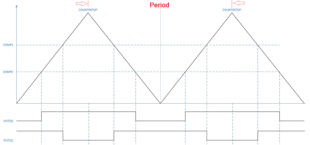

The period = 1 / 1MHz * 500 * 2 = 1ms (because top value = 500)
- The value of the COMP1 is 300. (40% duty cycle)
- The value of the COMP2 is 250. (50% duty cycle)
- where 0x8000 is the pin polarity
Complex Sequence Waveform
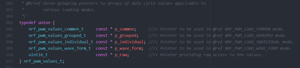
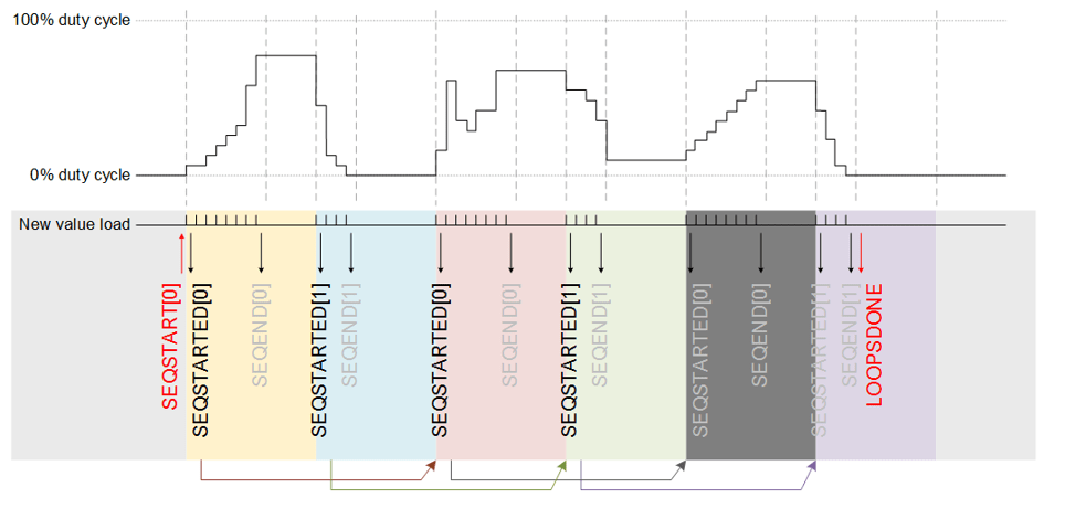
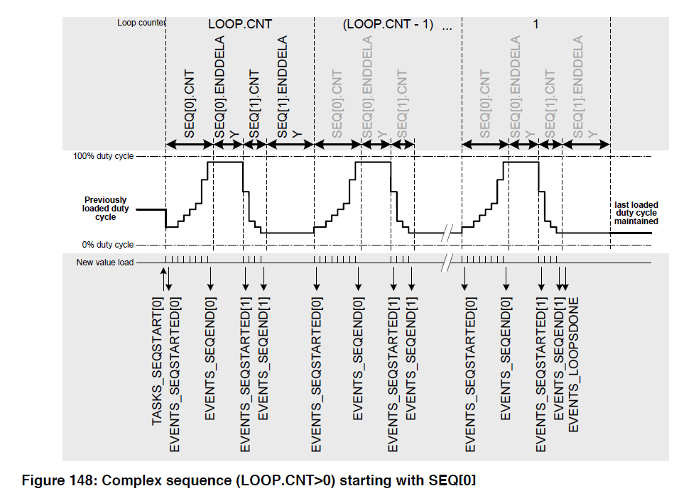
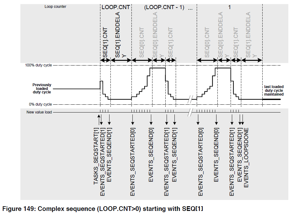
nRF52 can support a complex sequence waveform which plays from the Data RAM through DMA.

Decoder with EasyDMA
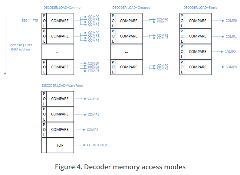
The decoder uses EasyDMA to take PWM parameters stored in RAM and update the internal compare registers of the wave counter, based on the mode of operation.
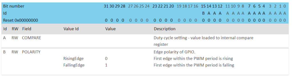
The DECODER register controls how the RAM content is interpreted and loaded into the internal compare registers. The LOAD field controls if the RAM values are loaded to all compare channels, or to update a group or all channels with individual values. The following figure illustrates how parameters stored in RAM are organized and routed to various compare channels in different modes:
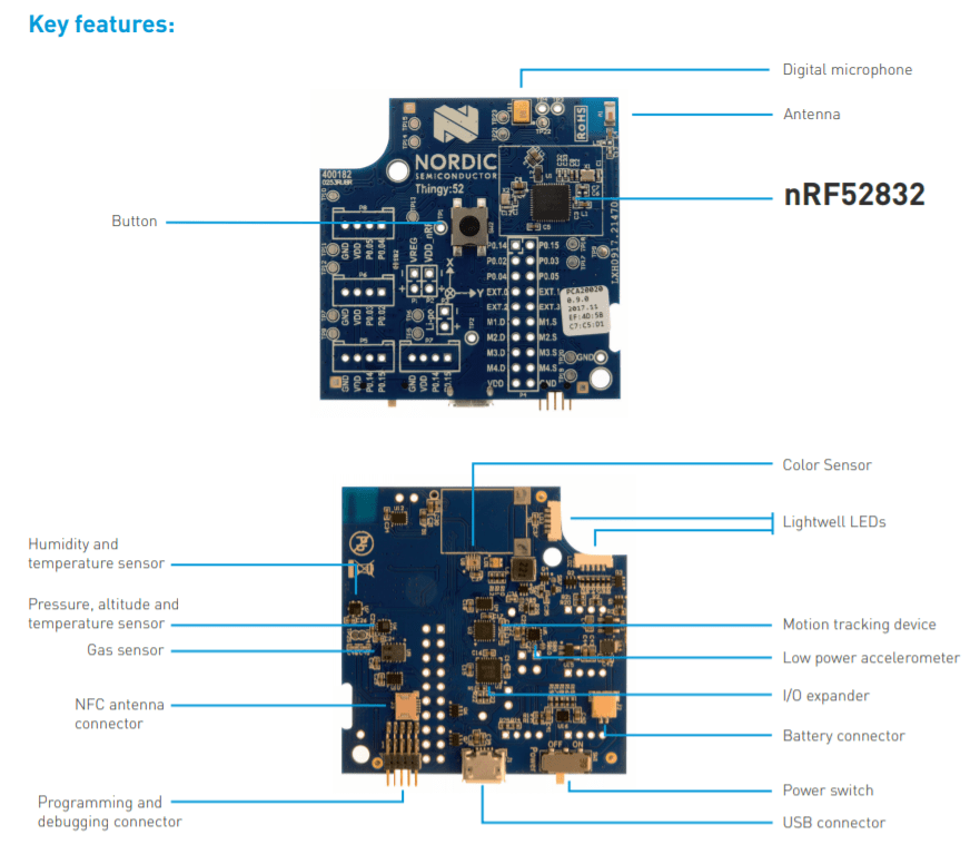
Nordic Thingy 52 provides a demo of how to use the PWM to play the low-quality sound.
Nordic Thingy 52
Nordic Thingy:52 is an easy-to-use development platform, designed to help you build IoT prototypes and demos, without the need to build hardware or write firmware from scratch.

Sound Service
The Sound service lets you control Thingy’s microphone (iOS and Android) and speaker. The Thingy Sound service is based on two building blocks, the speaker and the microphone, which can work in specific modes.
Speaker modes:
- 8-bit PCM (streaming)
- Frequency and duration (piano keyboard)
- Sample (sample sound effects)
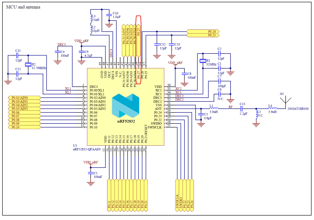
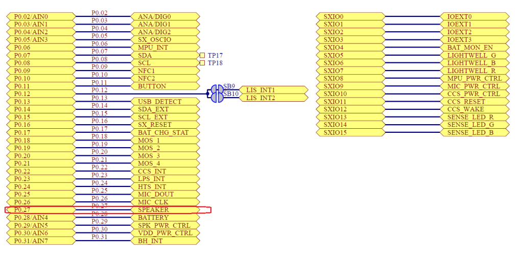
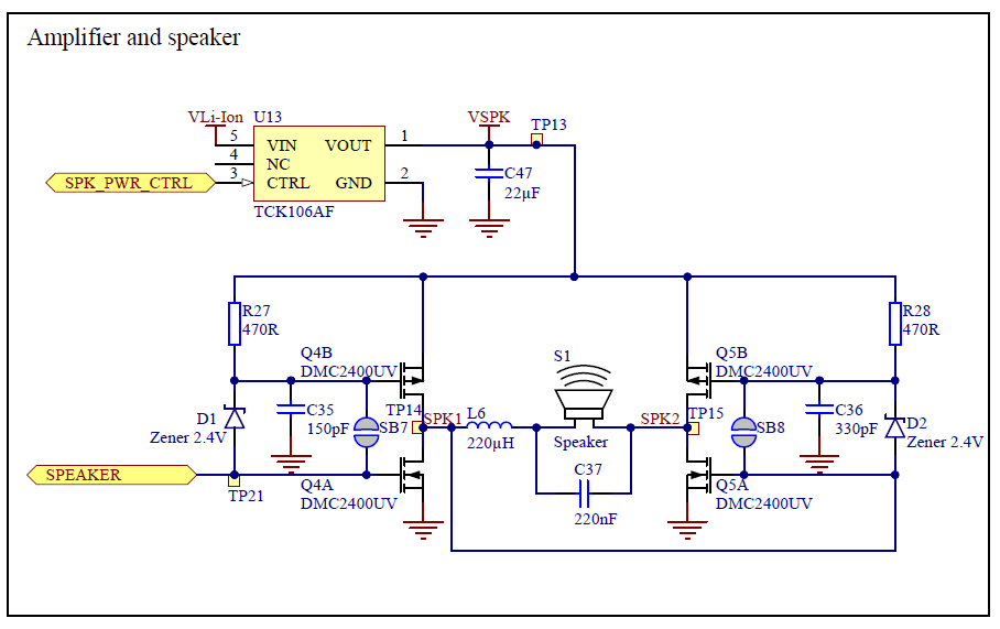
Inside the Thingy52 Schematics,
Firmware of the Thingy52
The firmware can be download at
https://www.nordicsemi.com/Software-and-tools/Prototyping-platforms/Nordic-Thingy-52/Download
Documentation of the Nordic Thingy52
https://nordicsemiconductor.github.io/Nordic-Thingy52-FW/documentation/index.html
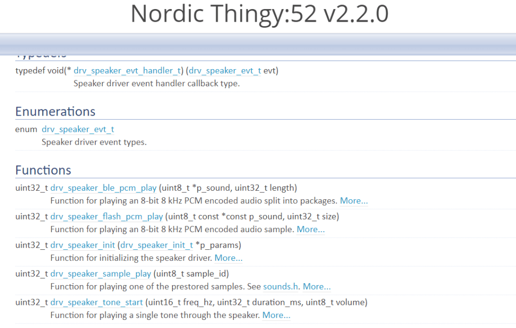
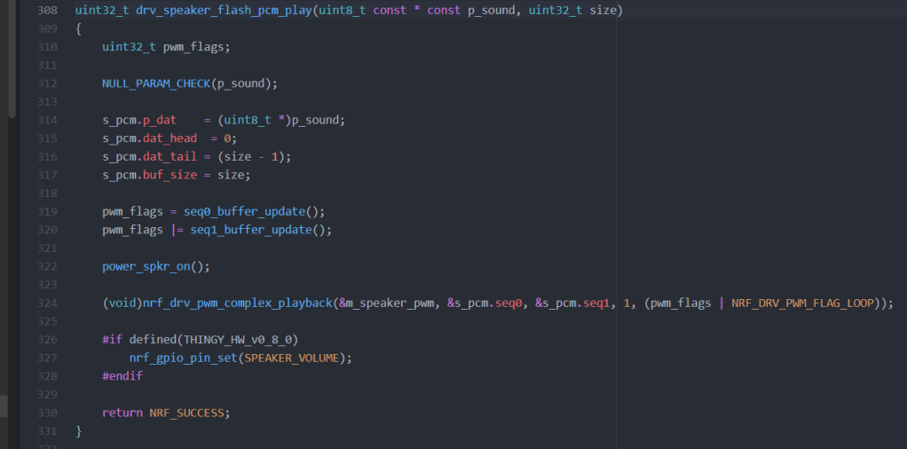
How to play the complex sound
- It is using the nrf_drv_pwm driver which is similar to the nrfx_pwm (after Nordic SDK 15.0 or later)
If you have any comments, welcome to leave them here.
Thanks for your interest in my blog. Since 2019, I have created this blog and shared the idea of how to do some funny stuff. I am very pleased that I get quite a lot of positive feedback. I really hope that this blog helps your own embedded solution development. May I get support from you to keep it in order to maintain the WordPress host service? Your appreciation would be very helpful.
https://jimmywongiot.com/2021/05/26/asking-for-support/


Like!! Great article post.Really thank you! Really Cool.
LikeLike
I had emailed Jimmy few times without getting any response. Now I realized this blog isn’t well maintained. These posts are just short snippets from Product Specification PDF. Reading the PDF is more useful.
LikeLike
Thank you Jimmy for the nice introduction which saves me from plenty pages of specification 🙂
LikeLike