This blog is to give you a guideline how to run the MCUBoot on the nRF Connect SDK / Zephyr RTOS at Nordic nRF52840 / nRF9160 chipset.
For example, the below is the modem FOTA upgrade at the nRF9160 chipset.

What is the MCUboot?
- MCUboot is a secure bootloader for 32-bit MCUs. The goal of MCUboot is to define a common infrastructure for the bootloader, system flash layout on microcontroller systems, and to provide a secure bootloader that enables simple software upgrades.
- MCUboot is operating system and hardware independent and relies on hardware porting layers from the operating. Currently, mcuboot works with both the Apache Mynewt and Zephyr operating systems,

boot_partition: for MCUboot itselfimage_0_primary_partition: the primary slot of Image 0image_0_secondary_partition: the secondary slot of Image 0scratch_partition: the scratch slot
The content of this blog are referred to some sources of online documentation as below.
- Building and using MCUboot with Zephyr (nRF Connect SDK)
https://developer.nordicsemi.com/nRF_Connect_SDK/doc/latest/mcuboot/readme-zephyr.html
- Building and using MCUboot with Zephyr (MCUBoot Github)
https://github.com/mcu-tools/mcuboot/blob/main/docs/readme-zephyr.md
- Device Firmware Upgrade (Zephyr online documentation)
https://docs.zephyrproject.org/latest/guides/device_mgmt/dfu.html?highlight=mcuboot
- MCUboot Walkthrough and Porting Guide (Interrupt)
https://interrupt.memfault.com/blog/mcuboot-overview
Online Video
Apart from the online documentation, you can refer to online video training (conducted by Linaro) at the Embedded Linux Conference @ 2018.
Building Applications for the bootloader
If you have a look on the nRF Connect SDK such as v1.5.1 release tag, it has the multiple folder.
Instructions for different operating systems can be found here:
- boot/bootutil: The core of the bootloader itself.
- boot/boot_serial: Support for serial upgrade within the bootloader itself.
- boot/zephyr: Port of the bootloader to Zephyr
- boot/mynewt: Mynewt bootloader app
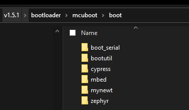
I would only focus on the boot/zephyr folder in this blog.

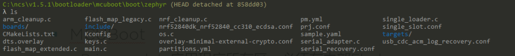
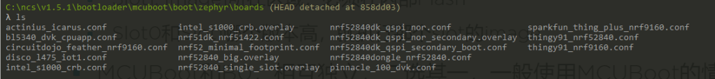
Inside the boot\zephyr\boards folder, you can find that there are multiple difference configurations such as nrf52_minimal_footprint.conf, nrf52840dk_qspi_nor.conf, nrf52840dk_qspi_secondary_boot.conf.
For example, there are two simple modes. You can select the difference configure file for difference option.
- Secondary slot at the internal flash
- Secondary slot at the external flash
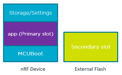
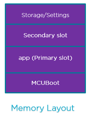
Partitions of Zephyr MCUBoot
- Boot_partition: for MCUBoot itself
- Bootloader location
- Image_0_primary_partition: the primary slot of Image 0 (Slot0_partition)
- MCUboot loads the executable application image from this partition. Any application bootable by MCUboot must be linked to run from this partition.
- Image_1_secondary_partition: the secondary slot of Image 0 (Slot1_partition)
- Store firmware upgrade images
- MCUBoot checks for upgrade images in this partition and then move them to slot0_partition for execution.
- Same size of Slot0_partition and Slot1_partition.
- Scratch_partition: the scratch slot Temporary storage while swapping the contents of slot0_partition and slot1_partition.

Image Header
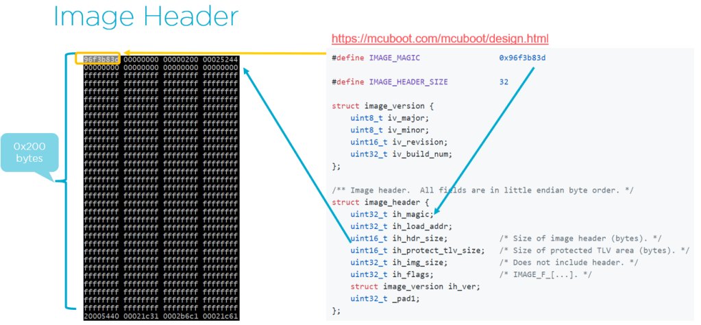
#define IMAGE_MAGIC                 0x96f3b83d

#define IMAGE_HEADER_SIZE           32

struct image_version {
    uint8_t iv_major;
    uint8_t iv_minor;
    uint16_t iv_revision;
    uint32_t iv_build_num;
};

/** Image header.  All fields are in little endian byte order. */
struct image_header {
    uint32_t ih_magic;
    uint32_t ih_load_addr;
    uint16_t ih_hdr_size; /* Size of image header (bytes). */
    uint16_t _pad2;
    uint32_t ih_img_size; /* Does not include header. */
    uint32_t ih_flags;    /* IMAGE_F_[...]. */
    struct image_version ih_ver;
    uint32_t _pad3;
};

/** Image TLV header.  All fields in little endian. */
struct image_tlv_info {
    uint16_t it_magic;
    uint16_t it_tlv_tot;  /* size of TLV area (including tlv_info header) */
};

/** Image trailer TLV format. All fields in little endian. */
struct image_tlv {
    uint8_t  it_type;   /* IMAGE_TLV_[...]. */
    uint8_t  _pad;
    uint16_t it_len;    /* Data length (not including TLV header). */
};

/*
 * Image header flags.
 */
#define IMAGE_F_PIC                      0x00000001 /* Not supported. */
#define IMAGE_F_NON_BOOTABLE             0x00000010 /* Split image app. */
#define IMAGE_F_RAM_LOAD                 0x00000020

/*
 * Image trailer TLV types.
 */
#define IMAGE_TLV_KEYHASH           0x01   /* hash of the public key */
#define IMAGE_TLV_SHA256            0x10   /* SHA256 of image hdr and body */
#define IMAGE_TLV_RSA2048_PSS       0x20   /* RSA2048 of hash output */
#define IMAGE_TLV_ECDSA224          0x21   /* ECDSA of hash output */
#define IMAGE_TLV_ECDSA256          0x22   /* ECDSA of hash output */
TLV (Type Length Value)
Optional type-length-value records (TLVs) containing image metadata are placed after the end of the image.
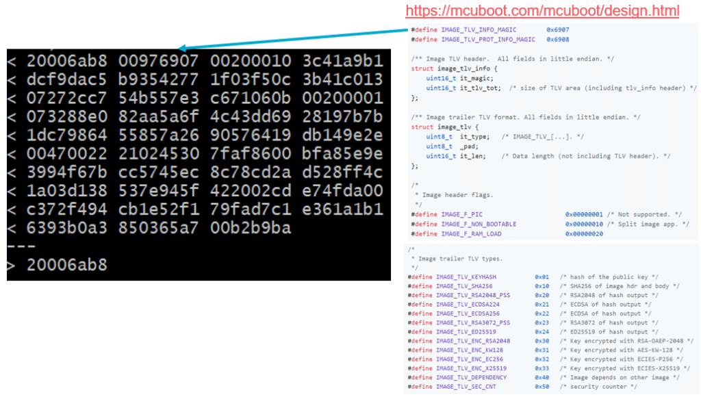
Image Trailer
For the bootloader to be able to determine the current state and what actions should be taken during the current boot operation, it uses metadata stored in the image flash areas. While swapping, some of this metadata is temporarily copied into and out of the scratch area.
This metadata is located at the end of the image flash areas, and is called an image trailer. An image trailer has the following structure:
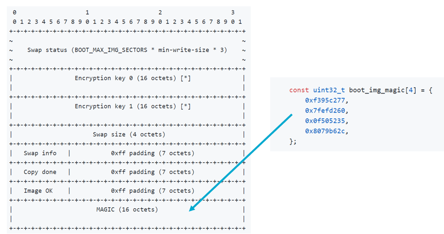
When the image is started, the bootloader would determine the boot swap type by checking the image tailters.
At startup, the boot loader determines the boot swap type by inspecting the image trailers. When using the term “image trailers” what is meant is the aggregate information provided by both image slot’s trailers.
Note: An important caveat about the tables described below is that they must be evaluated in the order presented here. Lower state numbers must have a higher priority when testing the image trailers.
    State I
                     | slot-0 | slot-1 |
    -----------------+--------+--------|
               magic | Any    | Good   |
            image-ok | Any    | Unset  |
           copy-done | Any    | Any    |
    -----------------+--------+--------'
     result: BOOT_SWAP_TYPE_TEST       |
    -----------------------------------'


    State II
                     | slot-0 | slot-1 |
    -----------------+--------+--------|
               magic | Any    | Good   |
            image-ok | Any    | 0x01   |
           copy-done | Any    | Any    |
    -----------------+--------+--------'
     result: BOOT_SWAP_TYPE_PERM       |
    -----------------------------------'


    State III
                     | slot-0 | slot-1 |
    -----------------+--------+--------|
               magic | Good   | Unset  |
            image-ok | 0xff   | Any    |
           copy-done | 0x01   | Any    |
    -----------------+--------+--------'
     result: BOOT_SWAP_TYPE_REVERT     |
    -----------------------------------'
More details such as Swap operation procedure, image status can be found at https://developer.nordicsemi.com/nRF_Connect_SDK/doc/0.3.0/mcuboot/design.html.
Procedure to build up the MCUBoot with Application
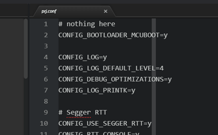
- Use the hello_world example from zephyr\sample\hello_world
- Add the switch “CONFIG_BOOTLOADER_MCUBOOT=y” inside the prj.conf
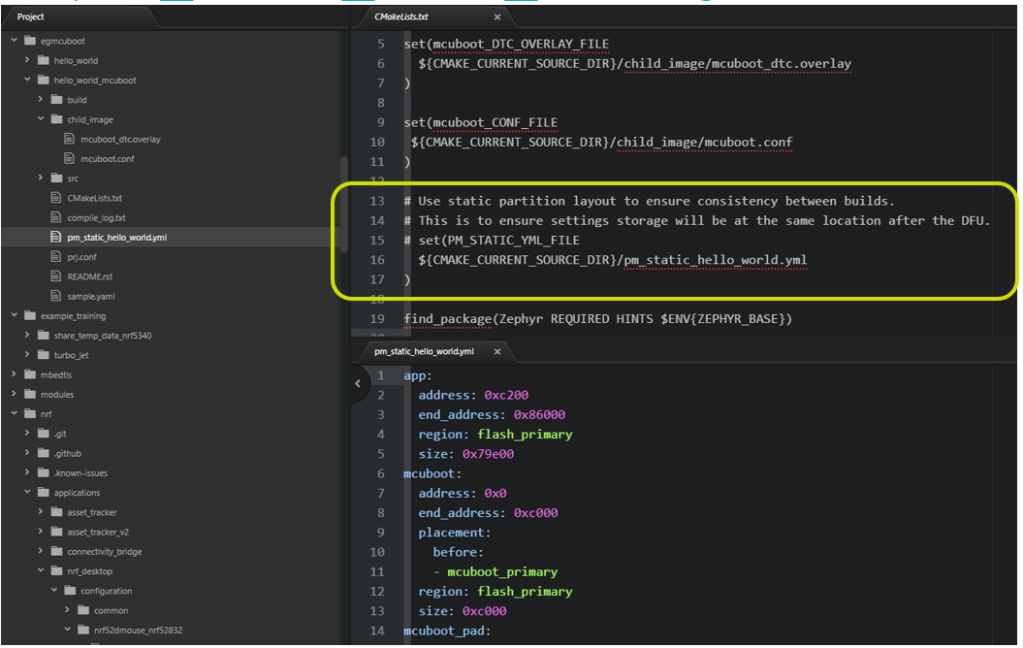
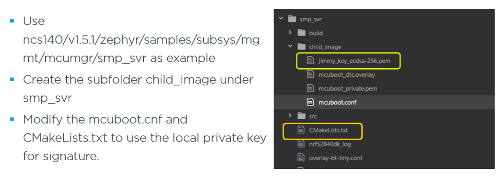
Create the local folder “child_image” instead of use the \bootloader\mcuboot\boot\zephyr (local mcuboot folder).

Use local mcuboot configuration and overlay file and modify the CMakeLists.txt
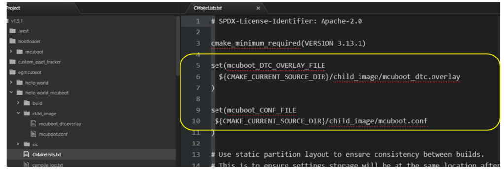
Build the image with MCUBoot

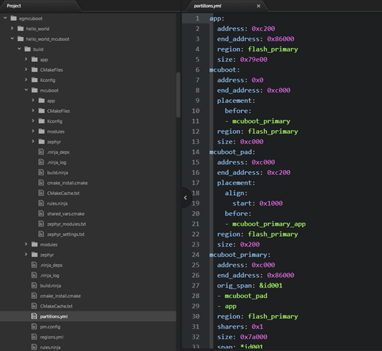
Partition Layout
Normally, the partition layout is configured by using the script (pm.yml) which define flash and RAM location.
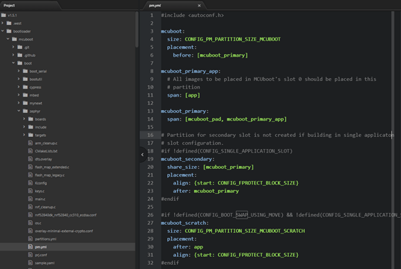
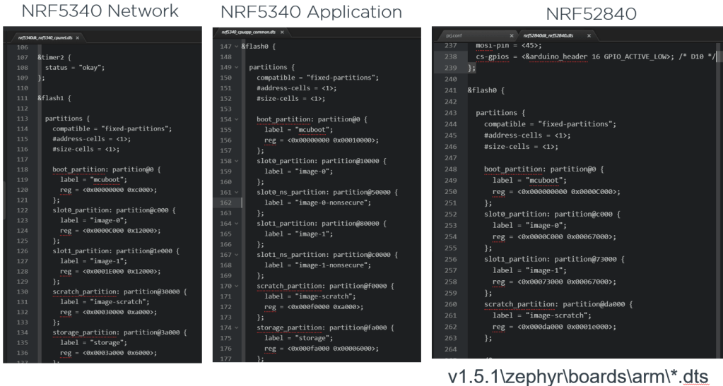
It has the default configuration pm.yml file inside the bootloader\mcuboot\boot\zephyr\pm.yml. It would read the .dts file on difference hardware configurations to get such address.
For example, there are 3 difference dts file for the nRF52840, nRF5340 network/application core.
If you need to use the custom partition layout, you can use the partitions.yml (generated from pm.yml) and rename it to pm_static.yml.

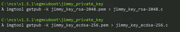
Imgtool (image tool)
The Python program scripts/imgtool.py can be used to perform the operations that are necessary to manage keys and sign images. Using this script should be preferred to the manual steps described in doc/signed_images.md.
https://developer.nordicsemi.com/nRF_Connect_SDK/doc/0.3.0/mcuboot/imgtool.html

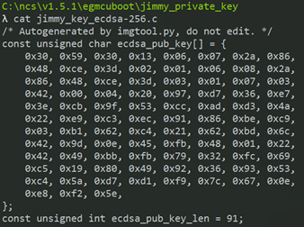
- Extracting the public key from private key
- Output the public key as a C array and store into the .c file.

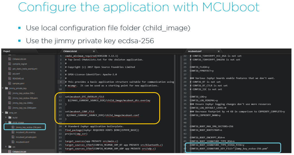
By using the West build, the image is automatic signed by the specified key as below.

Over the Air upgrade with Mobile
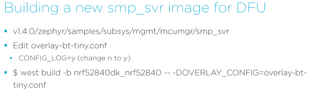
- If you need to use the mobile phone to perform the OTA, you need to select the example v1.5.1/zephyr/samples/subsys/mgmt/mcumgr/smp_svr.
- Then it generates the local private key and modify the corresponding .prj file.
- Save the signed smp_svr binary for use later
- cp build/zephyr/app_update.bin smp_svr_org.bin
- west flash
- will be flashed with merged.hex that contains MCUBoot and signed smp_svr


Welcome to give me any feedback and comment.
Thanks for your interests on my blog. Since 2019, I have created this blog and shared the idea how to do some funny stuffs. I am very pleasure that I get quite a lot of positive feedback. I really hope that this blog helps your own embedded solution development. May I get support from you to keep it in order to maintain the wordpress host service? Your appreciation would be very helpful.
https://jimmywongiot.com/2021/05/26/asking-for-support/


Hi, can you tell me where can I download Device Manager App?
LikeLike
I am often to running a blog and i really appreciate your content. The article has actually peaks my interest. I am going to bookmark your site and hold checking for new information.
LikeLike
Hi Jimmy, for the “building a new smp_svr image for DFU and uploading via Device Manager”.
Have you tried to rollback the image back to smp_svr once you’ve confirmed it?
Perhaps some API command available in mcuboot that allows to mark slot 1 (now smp_svr) as pending.
LikeLike
Hi Jimmy, cool page thanks!
But the first two images are maybe wrong?
It is mcuboot slot0 and slot1 and scratch but in your pictures it is shown slot1 slot0 is it meant than the swapping tokes place from bootloader already?
LikeLike