
This blog is to prepare the most common AT commands on nRF9160 and I will try to show how to use the at_client with link monitor for connecting the network.
https://infocenter.nordicsemi.com/topic/ref_at_commands/REF/at_commands/at_version.html
Modem firmware versions
This document describes AT commands used in all versions of the nRF91 Series modem firmware.
The modem firmware versions that support a command are marked in the command description with the following version tag: vx.x.x
If a parameter is not supported by all versions of the modem firmware that support the command, the modem firmware versions that support the parameter are marked after the parameter with the version tag.
The version tags are read as follows:
- If a command or parameter is markedv1.0.x, it is supported by modem firmware versions where the first two digits are 1 and 0.
- If a command is markedv1.0.xv1.1.xv1.2.x, it is supported by modem firmware versions where the first two digits are 1 and 0, 1 and 1, or 1 and 2.
- If a command or parameter is markedv1.1.x≥3, it is supported by modem firmware versions where the first two digits are 1 and 1 and the third digit is greater than or equal to 3.
- If a command or parameter is markedv1.1.3, it is supported only by modem firmware version 1.1.3.
The latest version of the Modem is
nRF9160 SiP modem firmware – what it is and how it works (Quick Update on the latest version of Modem firmware)
https://www.nordicsemi.com/Products/Low-power-cellular-IoT/nRF9160/

- Pre-compiled binary, signed and encrypted
- Update via PC tool nRF Connect for Desktop
- Secure boot with image authentication
- LTE Rel-13 Cat-M1 (LTE-M/eMTC)
- LTE Rel-13 Cat-NB1 (NB-IoT)
- Type B half duplex (HD), frequency division duplex (FDD)
- Cat-M1 operation is enabled on E-UTRA Bands 1, 2, 3, 4, 5, 8, 12, 13, 17, 18, 19, 20, 25, 26, 28 and 66.
- Cat-NB1 operation is enabled on E-UTRA Bands 1, 2, 3, 4, 5, 8, 12, 13, 17, 19, 20, 25, 26, 28 and 66.
- Power saving
- Power Save Mode (PSM)
- Idle-DRX and Connected Mode-DRX, DRX/extended-DRX in both
- Independent clock and sleep state control
- Interface to Application CPU
- AT-command Interface for control
- Socket Interface for Data
- Modem production test support
- Antenna Tuner per band Configurability with limited MIPI-RFFE support
- Integrated TLS(1.2)/DTLS(1.2) and TCP/UDP/IPV4/IPV6 Dual Stack
- Storage of TLS and Cloud credentials
- SMS PDU Mode
- Differential FOTA support enables small upgrade images
- Support for SIM ATK and remote provisioning via Bearer Independent Protocol
- eSIM support
- GPS L1 C/A positioning
- GPS L1 C/A receiver during LTE PSM and Idle DRX/extended-DRX modes
- Single shot, fixed interval and continuous tracking modes
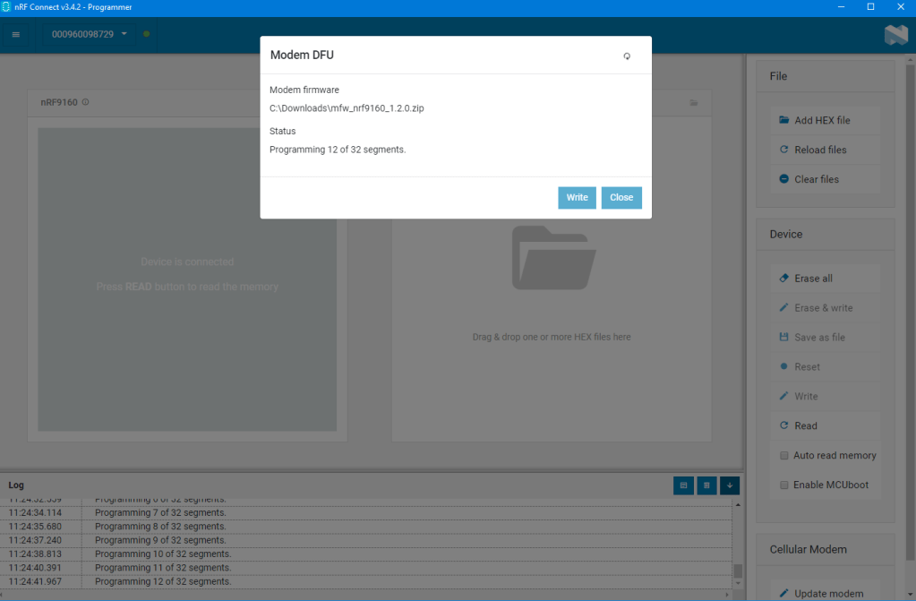
Upgrade the Modem firmware through nRF Connect Desktop (Programmer)
For example, it uses the programmer to download the latest LTE modem firmware (mfw_nrf9160_1.2.0.zip).
nRF91 AT Commands
This document describes the AT commands used to control the modem in nRF91 Series devices. The nRF91 series AT command API enables modem control for firmware running in the application core on nRF91 series devices.
The AT command API can also be exposed on one of the nRF91 serial interfaces by programming appropriate firmware in the application core. The nRF Connect SDK contains examples of such proxy firmware that can be run stand-alone or as part of other firmware functionality in the nRF91 application core. The stand-alone example is called at_client. This way, an external MCU or computer can get access to the modem API either exclusively or in addition to application firmware running on the nRF91 itself.
The AT commands described in this document apply to all versions of the nRF9160 module hardware. If a command applies only to a specific version of the module hardware, it is mentioned in the command description. The module hardware version is printed on the module label. For more information on nRF9160 module hardware versions, see nRF9160 Compatibility Matrix.
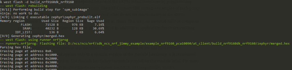
Program the at_client under the ncs\nrf\samples\nrf9160\at_client

I) General commands
| Description | Syntax | AT Command e.g. | |
| 1 | Request model identification +CGMM | +CGMM | AT+CGMM nRF9160-SICA OK |
| 2 | Request revision identification +CGMR | +CGMR | AT+CGMR mfw_nrf9160_1.1.1 OK |
| 3 | Request manufacturer identification +CGMI | +CGMI | AT+CGMI Nordic Semiconductor ASA OK |
| 4 | Request product serial number identification +CGSN | +CGSN[=] 0 – Respond with (default) 1 – Respond with +CGSN: 2 – Respond with +CGSN: 3 – Respond with +CGSN: | Reads the serial number AT+CGSN 352656100367872 OK Reads the IMEI: AT+CGSN=1 +CGSN: “352656100367872” OK |
| 5 | Request IMSI +CIMI | +CIMI [request] <IMSI> [response] IMSI, a string without double quotes | reads the IMSI string AT+CIMI 284011234567890 OK |
| 6 | Short software identification %SHORTSWVER (Proprietary) | %SHORTSWVER | AT%SHORTSWVER %SHORTSWVER: nrf9160_1.1.2 OK |
| 7 | Hardware identification %HWVERSION (Proprietary) | %HWVERSION | requests hardware identification AT%HWVERSION %HWVERSION: nRF9160 SICA B0A OK |
| 8 | Request modem build UUID %XMODEMUUID (Proprietary) | %XMODEMUUID | requests the UUID of a modem build AT%XMODEMUUID %XMODEMUUID: 25c95751-efa4-40d4-8b4a-1dcaab81fac9 OK |
| 9 | Request ICCID %XICCID (Proprietary) | %XICCID | requests the ICCID of the USIM card AT%XICCID %XICCID: 8901234567012345678F OK |
| 10 | Set and read ODIS fields +ODIS | +ODIS=,,, | sets host device ID to HDID01, host device manufacturer to HDMAN01, host device model to HDMOD01, and host device software version to HDSW01 AT+ODIS=”HDID01″,”HDMAN01″,”HDMOD01″,”HDSW01″ OK reads the current values AT+ODIS? +ODIS: “HDMAN01″,”HDMOD01″,”HDSW01” OK |
| 11 | Subscribe unsolicited ODIS notifications +ODISNTF | +ODISNTF=<reporting> | subscribes ODIS notificatons AT+ODISNTF=1 OK |
II) Mobile termination control and status commands
| Description | Syntax | AT Command (e.g.) | |
| 1 | Functional mode +CFUN | +CFUN=<FUN> 0 – Sets the device to minimum functionality. Disables both transmit and receive RF circuits and deactivates LTE and Global Navigation Satellite System (GNSS) services. 1 – Sets the device to full functionality. 4 – Sets the device to flight mode. Disables both transmit and receive RF circuits and deactivates LTE and GNSS services. 20 – Deactivates LTE without shutting down GNSS services. 21 – Activates LTE without changing GNSS. 30 – Deactivates GNSS without shutting down LTE services. 31 – Activates GNSS without changing LTE. 40 – Deactivates UICC. v1.1.x≥3 v1.2.x 41 – Activates UICC. v1.1.x≥3 v1.2.x 44 – Sets the device to flight mode without shutting down UICC. The read response parameter and its defined value is the following: <fun> 0 – Power off and store. RF circuits are disabled by deactivating LTE and GNSS services. 1 – Normal mode. The active mode is either LTE or GNSS, or both. Full functional mode. Active modes depend on %XSYSTEMMODE setting. 4 – Flight mode. RF circuits are disabled by deactivating LTE and GNSS services. | activates the modem Normal mode AT+CFUN=1 OK reads the current functional mode AT+CFUN? +CFUN: 1 OK |
| 2 | PIN code +CPIN | set command enters the PIN +CPIN=<pin>[,<newpin>] The read command checks if a PIN is needed or if a personalization lock is blocking the device start-up. +CPIN: | enter PIN 1234 AT+CPIN=”1234″ OK shows how to check if a PIN code is needed with the response that a PIN code is required: AT+CPIN? +CPIN: “SIM PIN” OK |
| 3 | Remaining PIN retries +CPINR | +CPINR command returns the number of remaining PIN retries for the UE passwords. +CPINR=<sel_code> | checks the remaining entries for PIN: AT+CPINR=”SIM PIN” +CPINR: “SIM PIN”,3 OK |
| 4 | List all available AT commands +CLAC | set command returns a list of all available AT commands. +CLAC | lists the supported AT commands: AT+CLAC AT+CFUN AT+COPS … OK |
| 5 | Extended signal quality +CESQ | The +CESQ command returns received signal quality parameters. +CESQ Response syntax: +CESQ, <rxlev>,<ber>, rscp>, <econ>,<rsrq>,<rsrp> | reads the current signal quality, mapped Reference Signal Received Quality (RSRQ) 31, and Reference Signal Received Power (RSRP) 62 AT+CESQ +CESQ: 99,99,255,255,31,62 OK returns supported values as compound values AT+CESQ=? +CESQ: (99),(99),(255),(255),(0-34,255),(0-97,255) OK |
| 6 | Signal quality notification %CESQ (proprietary) | The set command subscribes or unsubscribes notifications of changes in signal quality %CESQ=<n> notification syntax (response) %CESQ: <rsrp>,<rsrp_threshold_index>, <rsrq>, <rsrq_threshold_index> <n>, 0 – Unsubscribe signal quality notifications 1 – Subscribe signal quality notifications | subscribes E-UTRA signal quality notifications: AT%CESQ=1 OK indicates a change in the measured average RSRP. The average RSRP is 62 and mapped to threshold 3, the measured RSRQ average has been 12 and mapped to threshold index 1. %CESQ: 62,3,12,1 |
| 7 | Restricted SIM access +CRSM | set command transmits restricted commands to the SIM +CRSM=<command>,[,fileid>[,<P1>,<P2>,<P3>[,<data>[,<pathid>]]]] | reads the forbidden Public Land Mobile Network (PLMN) list: AT+CRSM=176,28539,0,0,12 +CRSM: 144,0,”64F01064F040FFFFFFFFFFFF” OK |
| 8 | Device activity status +CPAS | returns the device activity status. +CPAS | checks the activity status AT+CPAS +CPAS: 0 OK |
| 9 | Indicator control +CIND | +CIND command sets indicator states +CIND=[<ind>[,<ind>[,…]]] | enables service and message indicators: AT+CIND=1,0,1 OK returns indicator states. AT+CIND? +CIND: 1,0,1 OK |
| IP address format +CGPIAF | +CGPIAF command returns information about IPv6 address format | reads the current IPv6 address format: AT+CGPIAF? +CGPIAF: 1,1,1,0 OK | |
| Current band %XCBAND (Proprietary) | Nordic-proprietary %XCBAND command returns the current E-UTRA band %XCBAND | reads the current band: AT%XCBAND %XCBAND: 13 OK | |
| Read neighbor cells %NBRGRSRP (Proprietary) | reads measured RSRP values of neighboring cells. The command issues a valid response only when the modem is activated. %NBRGRSRP | read command is not supported | |
| Mode of operation (CS/PS) +CEMODE | sets the CS/PS Mode of Operation. The mode is stored in the non-volatile memory when the device is powered off with +CFUN=0. The command should only be used when the modem is not activated. +CEMODE=[<mode>] <mode> 0 – PS mode 2 of operation 2 – CS/PS mode 2 of operation | sets the operating mode to PS mode 2: AT+CEMODE=0 OK | |
| Modem trace activation %XMODEMTRAC (Proprietary) | %XBANDLOCK command sets locked bands. The band lock should be set before activating modem with +CFUN. %XBANKLOCK=<operation>[,<band_mask>] | sets permanent band 4 lock AT%XBANDLOCK=1,”1000″ OK sets runtime band 4 and 13 lock AT%XBANDLOCK=2,”1000000001000″ OK | |
| Data profile %XDATAPRFL (Proprietary) | provide information on the application use case to modem so that it can optimize power consumption. %XDATAPRFL=<power_level> 0 – Ultra-low power 1 – Low power 2 – Normal 3 – Performance 4 – High performance | Set a low power level AT%XDATAPRFL=1 OK | |
| Connectivity statistics %XCONNSTAT (Proprietary) | set command sets the connectivity statistics command. %XCONNSTAT=<command> 0 – Stop 1 – Start | makes the LwM2M application start and stop connectivity statistics AT%XCONNSTAT=1 OK AT%XCONNSTAT=0 OK | |
| Battery voltage %XVBAT (Proprietary) | The Nordic-proprietary %XVBAT command reads battery voltage. v1.0.x v1.1.x v1.2.x When the modem is active (either LTE communication or GPS receiver), the %XVBAT command returns the latest voltage measured automatically during modem wakeup or reception. The voltage measured during transmission is not reported. During modem inactivity, the modem measures battery voltage when the %XVBAT command is received. %XVBAT | reads the battery voltage in mV AT%XVBAT %XVBAT: 3600 OK Integer. Battery voltage in mV, with a resolution of 4 mV. | |
| Credential storage management %CMNG | writes, reads, deletes, and checks the existence of keys and certificates. The credentials are stored in the non-volatile memory %CMNG=<opcode>[,<sec_tag>[,<type>[,<content>[,<passwd>]]]] | writes the root certificate AT%CMNG=0, 12345678, 0,” —–BEGIN CERTIFICATE—– MIIDSjCCA… …bKbYK7p2CNTUQ —–END CERTIFICATE—–” OK writes the client certificate AT%CMNG=0,567890,1,” —–BEGIN CERTIFICATE—– MIIBc464… …bW9aAa4 —–END CERTIFICATE—–” OK | |
| System mode %XSYSTEMMODE (proprietary) | sets the modem system mode %XSYSTEMMODE-=<M1_support>, <NB1_support>, <GNSS_support>, <LTE_perference> +CME Error codes 518 – Not allowed in active state 522 – Band configuration not valid for selected mode | sets LTE Cat-M1 and GNSS as the system modes AT%XSYSTEMMODE=1,0,1,0 OK reads the supported system mode AT%XSYSTEMMODE? %XSYSTEMMODE: 1,0,0,0 OK |
Network service related commands
| Description | Syntax | AT Command e.g. | |
| PLMN selection +COPS | selects a PLMN automatically or manually, and reads and searches the current mobile network. +COPS=[<mode>[,<format>[,<oper>]]] <mode> 0 – Automatic network selection 1 – Manual network selection 3 – Set of +COPS read command response. <format> 0 – Long alphanumeric format. Only for 3. 1 – Short alphanumeric format. Only for 3 . 2 – Numeric format <oper> String. Mobile Country Code (MCC) and Mobile Network Code (MNC) values. Only numeric string formats supported. | selects the automatic network selection AT+COPS=0 OK manually selects network 24407 AT+COPS=1,2,”24407″ OK reads the current selection mode and network AT+COPS? +COPS: 0,2,”26201″,7 OK reads the current selection mode and network with the operator name in the alphanumeric format AT+COPS? +COPS: 0,0,”RADIOLINJA”,7 OK | |
| Forced PLMN search %COPS (Proprietary) | performs a forced PLMN search %COPS | manual network search AT%COPS=? %COPS: (2,””,””,”26201″,7),(1,””,””,”26202″,7) OK | |
| Power saving mode setting +CPSMS | +CPSMS command controls PSM settings +CPSMS=[<mode>[,<Requested_Periodic-RAU>,<Requested_GPRS-READY-timer> ,<Requested_Periodic-TAU>[,<Requested_Active-Time>]]] reads the current PSM settings AT+CPSMS? | enables power saving mode and set timer values. Set Periodic-TAU timer to 10 minutes and Active-Time to 1 minute. AT+CPSMS=1,””,””,”10101010″,”00100001″ OK disables power saving mode AT+CPSMS=0 OK disables power saving mode and sets timer to default values AT+CPSMS= OK reads the current power saving mode settings AT+CPSMS? +CPSMS: 1,,,”10101111″,”01101100″ OK | |
| eDRX setting +CEDRXS | +CEDRXS command controls the setting of eDRX parameters sets the requested eDRX parameters +CEDRXS=[<mode>,[,<AcT-type>[,<Requested_eDRX_value>]]] +CEDRXS: <AcT-type>,<Requested_eDRX_value> | Set: enables eDRX and sets the requested eDRX value AT+CEDRXS=1,4,”1000″ OK unsolicited notification when 2 is used +CEDRXP: 4,”1000″,”0101″,”1011″ OK Read: reads the requested eDRX value AT+CEDRXS? +CEDRXS: 4,”0001″ OK | |
| Read EDRX dynamic parameters +CEDRXRDP | +CEDRXRDP command reads dynamic eDRX parameters +CEDRXRDP | reads eDRX parameters AT+CEDRXRDP +CEDRXRDP: 4,”0011″,”0010″,”1001″ OK | |
| Read operator name +COPN | reads operator names +COPN | AT+COPN OK | |
| Network registration status +CEREG | +CEREG command subscribes unsolicited network status notifications Set +CEREG=<n> Read | Set: subscribes notifications with level 2: AT+CEREG=2 OK Read: reads the current registration status AT+CEREG? +CEREG: 2,1,”002F”,”0012BEEF”,7 OK | |
| Operator ID %XOPERID | set command returns the operator ID. %XOPERID %XOPERID:<oper_id> [response] 0 – Operator not identified as any of those listed below. 1 – Verizon 2 – AT&T 3 – AT&T FirstNet 4 – AT&T Cricket 5 – AT&T Jasper 6 – China Telecom 7 – Softbank 8 – Telstra | returns the operator ID: AT%XOPERID %XOPERID: 1 OK | |
| Read modem parameters %XMONITOR (proprietary) | %XMONITOR command reads a set of modem parameters Set command %XMONITOR: <reg_status>,[<full_name>,<short_name>,<plmn>,<tac>,<AcT>,<band>,<cell_id>, <phys_cell_id>,<EARFCN>,<rsrp>,<snr>,<NW-provided_eDRX_value>,<Active-Time>,<Periodic-TAU>] | reads modem parameters AT%XMONITOR %XMONITOR: 1,”EDAV”,”EDAV”,”26295″,”00B7″,7,4,”00011B07″,7,2300,63,39,””, “11100000”,”11100000″,”00000000″ OK | |
| Mobile network operator %XOPCONF (proprietary) | onfigures modem for the selected mobile network operator. v1.1 %XOPCONF=<op_conf> 1 – Automatically detected from IMSI 2 – Verizon 3 – AT&T 4 – China Telecom 5 – Softbank 6 – Telstra 7 – Bell 8 – LGU+ | sets Verizon operator configuration AT%XOPCONF=2 OK reads the configured operator AT%XOPCONF? AT%XOPCONF: 2 OK |
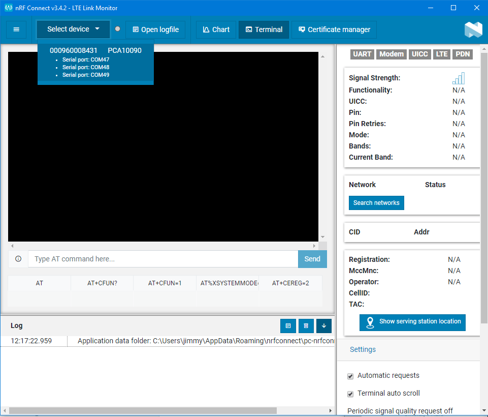
Trouble-Shoot with LTE Link Monitor (Step by Step AT command)
LTE Link Monitor is a modem client application that monitors the modem/link status and activity using AT commands.
See the nRF91 AT Commands Reference Guide for the AT commands that are supported by the modem in nRF91 Series devices.
LTE Link Monitor is implemented as an app for the nRF Connect for Desktop application.
Open the LTE Link Monitor

Step 1:
Switch the modem to flight mode
AT+CFUN=4
+CFUN=<FUN>
0 – Sets the device to minimum functionality. Disables both transmit and receive RF
circuits and deactivates LTE and Global Navigation Satellite System (GNSS) services.
1 – Sets the device to full functionality.
4 – Sets the device to flight mode. Disables both transmit and receive RF circuits
and deactivates LTE and GNSS services.
20 – Deactivates LTE without shutting down GNSS services.
21 – Activates LTE without changing GNSS.
30 – Deactivates GNSS without shutting down LTE services.
31 – Activates GNSS without changing LTE.
40 – Deactivates UICC. v1.1.x≥3 v1.2.x
41 – Activates UICC. v1.1.x≥3 v1.2.x
44 – Sets the device to flight mode without shutting down UICC.
Step 2:
sets the modem system mode
Only one supported LTE mode allowed at a time. This command is allowed only before
activating the modem using the CFUN=1 command. If the mode needs to be changed,the modem
must first be set to flight mode using the CFUN=4 command.
%XSYSTEMMODE=<M1_support>,<NB1_support>,<GNSS_support>,<LTE_preference>
+CME error codes
518 – Not allowed in active state
522 – Band configuration not valid for selected mode
The set command parameters and their defined values are the following:
<M1_support>
0 – LTE Cat-M1 not supported
1 – LTE Cat-M1 supported
<NB1_support>
0 – LTE Cat-NB1 not supported
1 – LTE Cat-NB1 supported
<GNSS_support>
0 – GNSS not supported
1 – GNSS supported
<LTE_preference>
<LTE preference> is for the coming releases. Not relevant in the current release.
0 – No preference
1 – LTE Cat-M1 preferred
2 – LTE Cat-NB1 preferred
The following command example sets LTE Cat-M1 and GNSS as the system modes. No preferred LTE mode set:
#sets LTE Cat-NB1 in system modes. No preferred LTE mode
 set
AT%XSYSTEMMODE=0,1,0,0
OK
Step 3:
Network registration status +CEREG (for debugging)
Syntax:
+CEREG=<n>
<n>
0 – Disable unsolicited result codes
1 – Enable unsolicited result codes +CEREG:<stat>
2 – Enable unsolicited result codes +CEREG:<stat>[,<tac>,<ci>,<AcT>]
3 – Enable unsolicited result codes
+CEREG:<stat>[,<tac>,<ci>,<AcT>[,<cause_type>,<reject_cause>]]
4 – Enable unsolicited result codes +CEREG: <stat>[,[<tac>],[<ci>],
[<AcT>][,,[,[<Active-Time>],[<Periodic-TAU>]]]]
5 – Enable unsolicited result codes +CEREG: <stat>[,[<tac>],[<ci>],
[<AcT>][,[<cause_type>],[<reject_cause>][,[<ActiveTime>],[<Periodic-TAU>]]]]
#subscribes notifications with level 2:
#2 – Enable unsolicited result codes
AT+CEREG=2
OK

#subscribes notifications with level 5:
#5 – Enable unsolicited result codes
AT+CEREG=2
OK
Step 4:
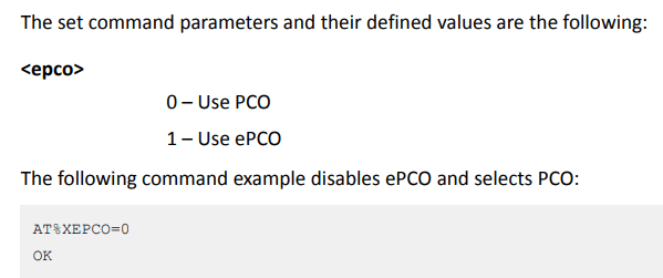
Usage of ePCO/PCO in PDN connection establishment %XEPCO (depend on the operator)
ePCO (extended protocol configuration options)
https://itectec.com/spec/8-128-extended-protocol-configuration-options-epco/
https://www.sharetechnote.com/html/Handbook_LTE_ProtocolConfigurationOption.html
Syntax:
%XEPCO=<epco>
Step 5:
Enable the modem
# 1 – Sets the device to full functionality.
AT+CFUN=1
You can also send the AT+CFUN? to get the modem status.
After done, it would successfully connect to HK CSL Limited operator NBIOT station.

