This blog is to describe how to setup the development environment for ESP32-S2-Kaluga DK Board.
The official documentation of the ESP32 S2 is placed at
The ESP32-S2-Kaluga-1 kit is a development kit by Espressif that is mainly created to:
- Demonstrate the ESP32-S2’s human-computer interaction functionalities
- Provide the users with the tools for development of human-computer interaction applications based on the ESP32-S2

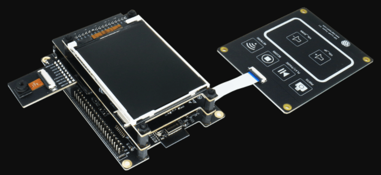
The ESP32-S2-Kaluga-1 kit consists of the following boards:
- Main board: ESP32-S2-Kaluga-1
- Extension boards:
- ESP-LyraT-8311A audio player
- ESP-LyraP-TouchA touch panel
- ESP-LyraP-LCD32 3.2” LCD screen
- ESP-LyraP-CAM camera board
Overview
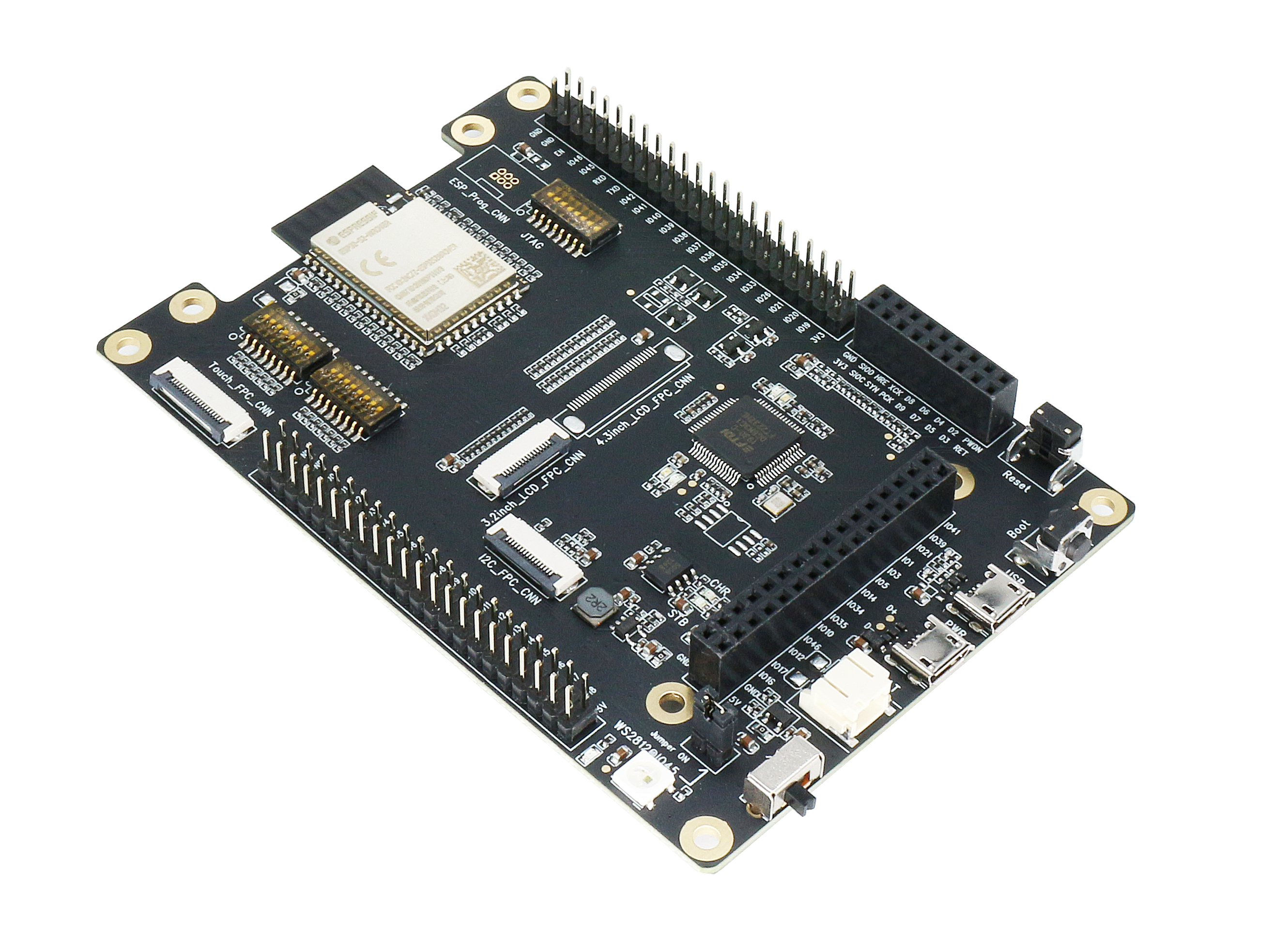
The ESP32-S2-Kaluga-1 main board is the heart of the kit. It integrates the ESP32-S2-WROVER module and all the connectors for extension boards. This board is the key tool in prototyping human-computer interaction interfaces.
The ESP32-S2-Kaluga-1 board has connectors for:
- Boards with the Extension Header (ESP-LyraT-8311A, ESP-LyraP-LCD32)
- Camera board (ESP-LyraP-CAM)
- Touch panel (ESP-LyraP-TouchA)
- LCD displays (no official extension boards yet)
- I2C devices (no official extension boards yet)
All the four extension boards are specially desgined to support the following features:
- Touch panel control
- 14 touch sensors, three of which support distance sensing (proximity mode)
- Supports acrylic panels up to 5 mm
- Wet hand operation
- Water rejection, ESP32-S2 can be configured to disable all touchpads automatically if multiple pads are simultaneously covered with water and to re-enable touchpads if the water is removed
- Audio playback
- Connect speakers to play audio
- Use together with the Touch panel to control audio playback and adjust volume
- LCD display
- LCD interface (8-bit parallel RGB, 8080, and 6800 interface)
- Camera image acquisition
- Supports OV2640 and OV3660 camera modules
- 8-bit DVP image sensor interface (ESP32-S2 also supports 16-bit DVP image sensors, you can design it yourself)
- Clock frequency up to 40 MHz
- Optimized DMA transmission bandwidth for easier transmission of high-resolution images
Description of Components
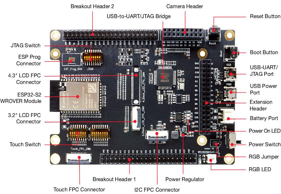
The description of components starts from the ESP32-S2 module on the left side and then goes clockwise.
Reserved means that the functionality is available, but the current version of the kit does not use it.
| Key Component | Description |
|---|---|
| ESP32-S2-WROVER Module | Module integrating the ESP32-S2 chip that provides Wi-Fi connectivity, data processing power, and flexible data storage |
| 4.3” LCD FPC Connector | (Reserved) Connect to a 4.3” LCD extension board using the FPC cable |
| ESP Prog Connector | (Reserved) Connection for Espressif’s download device (ESP-Prog) to flash ESP32-S2 system |
| JTAG Switch | Switch to ON to enable connection between ESP32-S2 and FT2232 |
| Breakout Header 2 | Some GPIO pins of the ESP32-S2-WROVER module are broken out to this header, see labels on the board |
| USB-to-UART/JTAG Bridge | FT2232 adapter board allowing for communication over USB port using UART/JTAG protocols |
| Camera Header | Mount a camera extension board here (e.g., ESP-LyraP-CAM) |
| Extension Header | Mount the extension boards having such connectors here |
| Reset Button | Press this button to restart the system |
| Boot Button | Holding down Boot and then pressing Reset initiates Firmware Download mode for downloading firmware through the serial port |
| USB-UART/JTAG Port | Communication interface (UART or JTAG) between a PC and the ESP32-S2 module |
| USB Power Port | Power supply for the board |
| Battery Port | Connect an external battery to the 2-pin connector |
| Power Switch | Switch to ON to power the system |
| RGB Jumper | To have access to the RGB LED, place a jumper onto the pins |
| RGB LED | Programmable RGB LED and controlled by GPIO45. Before using it, you need to put RGB Jumper ON. |
| Power Regulator | Regulator converts 5 V to 3.3 V |
| I2C FPC Connector | (Reserved) Connect to other I2C extension boards using the FPC cable |
| Breakout Header 1 | Some GPIO pins of the ESP32-S2-WROVER module are broken out to this header, see labels on the board |
| Touch FPC Connector | Connect the ESP-LyraP-TouchA extension board using the FPC cable |
| Touch Switch | In OFF position, GPIO1 to GPIO14 are used for connection to touch sensors; switch to ON if you want to use them for other purposes |
| 3.2” LCD FPC connector | Connect a 3.2” LCD extension board (e.g., ESP-LyraP-LCD32) using the FPC cable |
Hardware Reference
Block Diagram
A block diagram below shows the components of the ESP32-S2-Kaluga-1 and their interconnections.
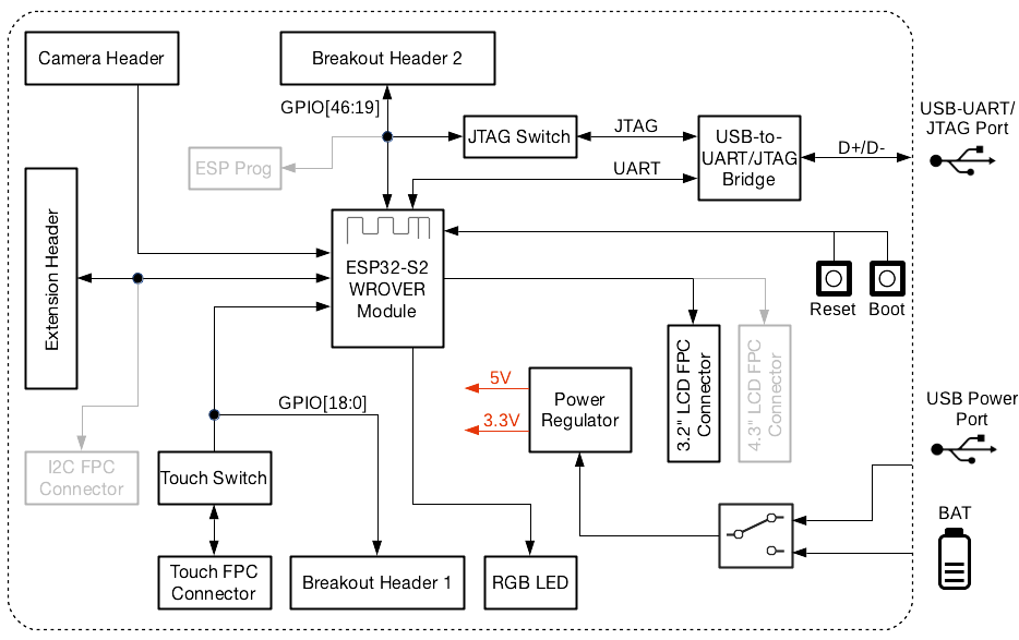
Power Supply Options
There are four ways to provide power to the board:
- Micro USB port, default power supply
- External battery via the 2-pin BAT connector
- 5V and GND header pins
- 3V3 and GND header pins
Environment Setup
Please proceed to Get Started, where Section Installation Step by Step will quickly help you set up the development environment.
The programming guide and application examples for your ESP32-S2-Kaluga-1 kit can be found here.
https://docs.espressif.com/projects/esp-idf/en/latest/esp32s2/get-started/index.html
Installation Step by Step
This is a detailed roadmap to walk you through the installation process.
Setting up Development Environment
- Step 1. Install prerequisites for Windows, Linux, or macOS
- Step 2. Get ESP-IDF
- Step 3. Set up the tools
- Step 4. Set up the environment variables
Creating Your First Project
- Step 5. Start a Project
- Step 6. Connect Your Device
- Step 7. Configure
- Step 8. Build the Project
- Step 9. Flash onto the Device
- Step 10. Monitor
Windows
In addition to installing the tools, ESP-IDF Tools Installer for Windows introduced in Step 1 can also download a copy of ESP-IDF.
Consult ESP-IDF Versions for information about which ESP-IDF version to use in a given situation.
If you wish to download ESP-IDF without the help of ESP-IDF Tools Installer, refer to these instructions.
Standard Setup of Toolchain for Windows
Introduction
ESP-IDF requires some prerequisite tools to be installed so you can build firmware for supported chips. The prerequisite tools include Python, Git, cross-compilers, CMake and Ninja build tools.
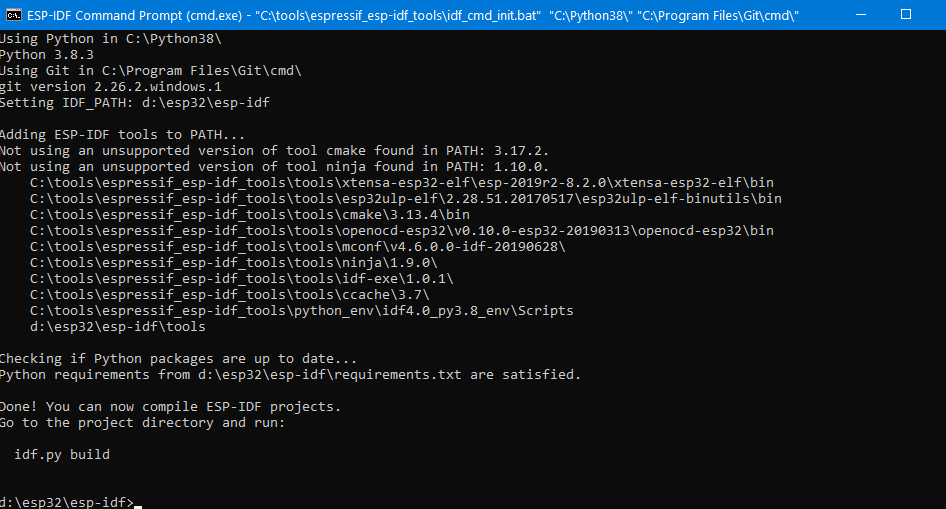
For this Getting Started we’re going to use the Command Prompt, but after ESP-IDF is installed you can use Eclipse or another graphical IDE with CMake support instead.
ESP-IDF Tools Installer
The easiest way to install ESP-IDF’s prerequisites is to download the ESP-IDF Tools installer from this URL:
https://dl.espressif.com/dl/esp-idf-tools-setup-2.3.exe
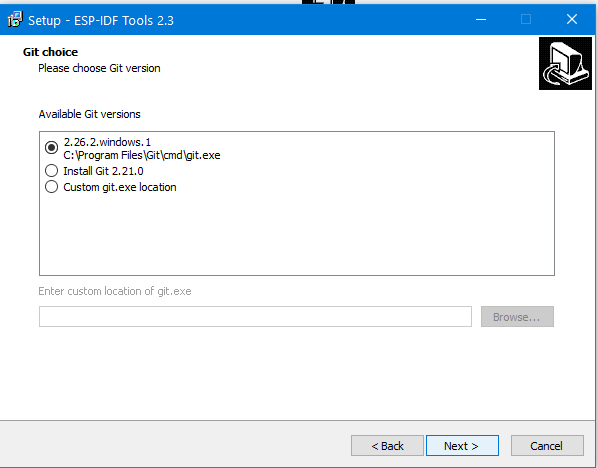
The installer includes the cross-compilers, OpenOCD, cmake and Ninja build tool. The installer can also download and run installers for Python 3.7 and Git For Windows if they are not already installed on the computer.
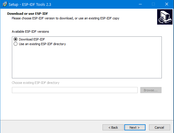
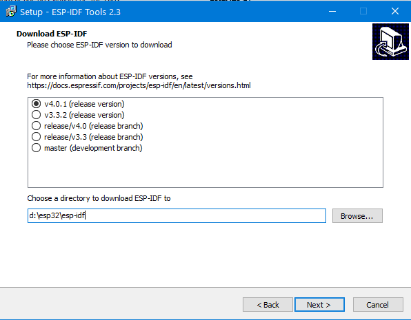
The installer also offers to download one of the ESP-IDF release versions.
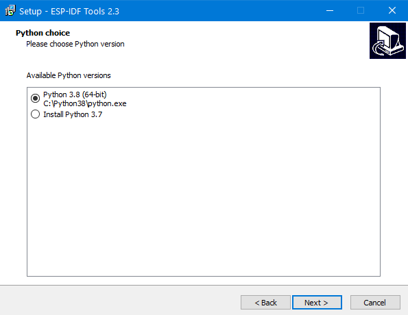
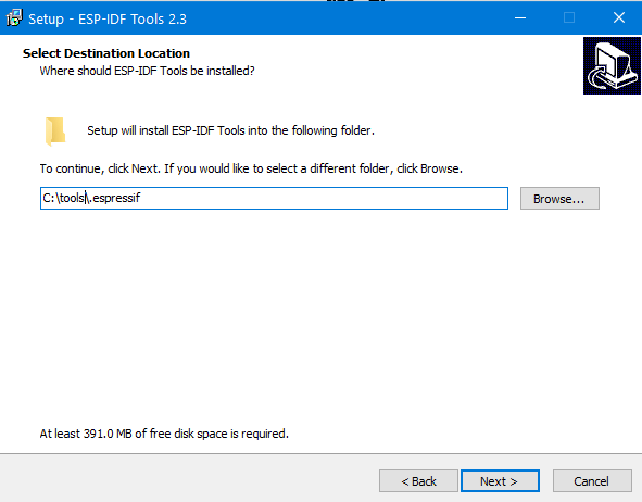
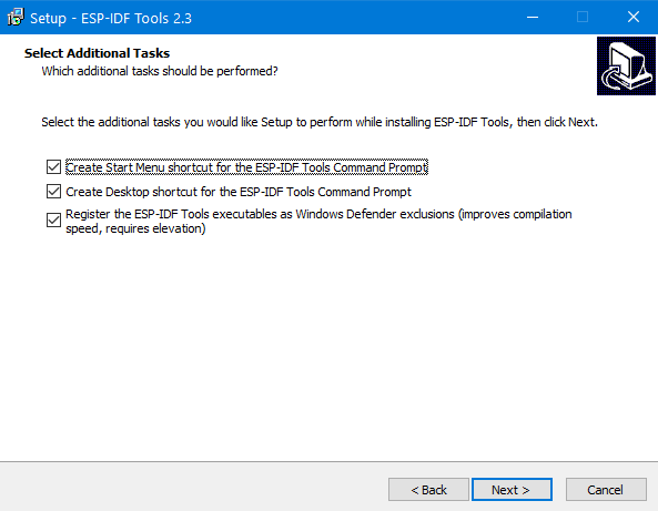
Installation on esp-idf-tools-setup
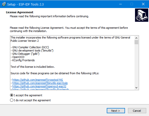
Select the python version (for example, if you have python before).
How to use the IDE Eclipse
https://github.com/espressif/idf-eclipse-plugin/blob/master/README.md
Demo Code
https://github.com/espressif/esp-dev-kits/tree/master/esp32-s2-kaluga-1

You just posted what was on Espressif own sites and linked to there GitHub examples. nothing new!
Have you got how to put text on Kaluga LCD, Read hard switches, play a sound, read write to flash, add on SDcard, FS system and read/write to ESP 32 S2 hardware on Kaluga…. No!
So you add nothing!
LikeLike
I tried to run on such demo through their docs. But it failed to setup. Details you can find in.
https://www.esp32.com/viewtopic.php?f=13&t=16920&p=64806&hilit=can%27t+run+the+original+demo+on+ESP32+S2+Kaluga+1+DK#p64806
LikeLike