
This blog is to introduce how to use the EasyDMA on TWI with Arraylist in order to reduce the MCU wake up and interrupt latency.
There are quite a lot of discussion on the devzone past few years.
- https://devzone.nordicsemi.com/f/nordic-q-a/48198/spi-communication-via-dma-in-background-using-ppi-and-a-timer/
- https://devzone.nordicsemi.com/f/nordic-q-a/51889/nrf52832-dma-half-transfer-interrupt-and-easydma-arraylist
- https://devzone.nordicsemi.com/f/nordic-q-a/18919/how-to-use-spim-easydma-with-nrf52
EasyDMA
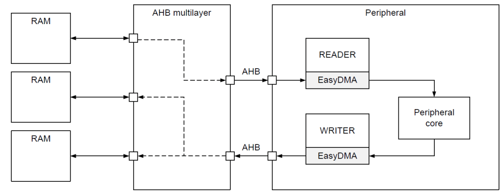
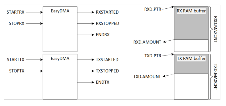
EasyDMA is a module implemented by some peripherals to gain direct access to Data RAM.
EasyDMA is an AHB bus master similar to CPU and is connected to the AHB multilayer interconnect for
direct access to Data RAM. EasyDMA is not able to access flash.
A peripheral can implement multiple EasyDMA instances to provide dedicated channels. For example, for reading and writing of data between the peripheral and RAM. This concept is illustrated in EasyDMA example.
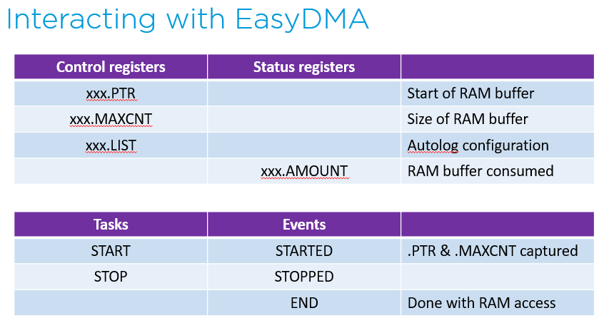
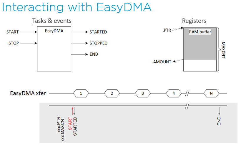
An EasyDMA channel is implemented in the following way, but some variations may occur:
READERBUFFER_SIZE 5
WRITERBUFFER_SIZE 6
uint8_t readerBuffer[READERBUFFER_SIZE] __at__ 0x20000000;
uint8_t writerBuffer[WRITERBUFFER_SIZE] __at__ 0x20000005;
// Configuring the READER channel
MYPERIPHERAL->READER.MAXCNT = READERBUFFER_SIZE;
MYPERIPHERAL->READER.PTR = &readerBuffer;
// Configure the WRITER channel
MYPERIPHERAL->WRITER.MAXCNT = WRITEERBUFFER_SIZE;
MYPERIPHERAL->WRITER.PTR = &writerBuffer;
This example shows a peripheral called MYPERIPHERAL that implements two EasyDMA channels – one for reading called READER, and one for writing called WRITER. When the peripheral is started, it is assumed that the peripheral will:
• Read 5 bytes from the readerBuffer located in RAM at address 0x20000000.
• Process the data.
• Write no more than 6 bytes back to the writerBuffer located in RAM at address 0x20000005.
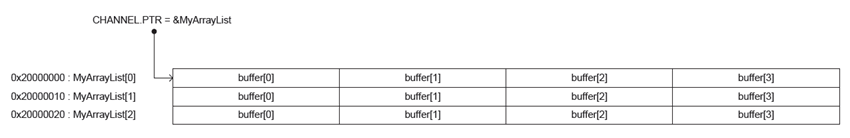
EasyDMA array list
- EasyDMA is able to operate in Array List mode.
- The Array List mode is implemented in channels where the LIST register is available.
- The array list does not provide a mechanism to explicitly specify where the next item in the list is located.
- Instead, it assumes that the list is organized as a linear array where items are located one after the other in RAM.
- Available for SPIM and TWIM
- Auto-increment of EasyDMA address pointer
- Allows fully automated sensor data collection, through use of PPI
- Assumes a known data packet size, not changing over time

EXAMPLE
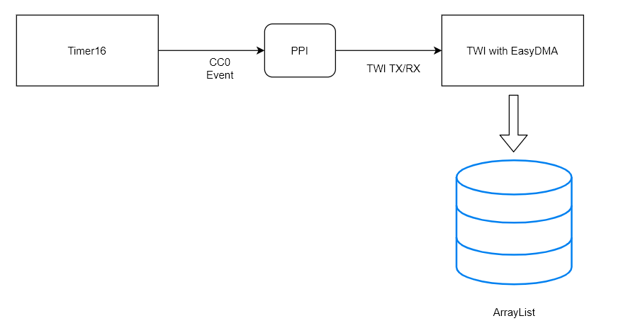
The example of this blog is to use the timer16 for regularly triggering the TWI for read the touch sensor data. I use the Adafruit LCD 1947 display ( https://www.adafruit.com/product/1947) with nRF52840 for demo. I use the touch sensor FT6206.
Here is the block diagram which I plan to show.
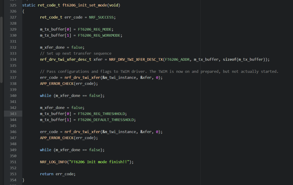
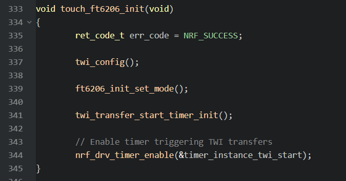
Initialize the FT6206 Touch Sensor
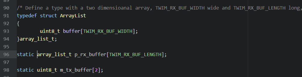
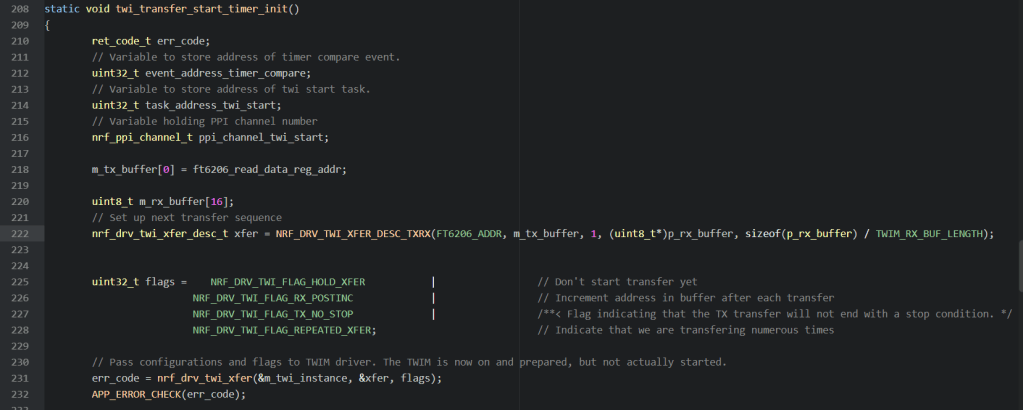
Define a type with a two dimensioanal array, TWIM_RX_BUF_WIDTH wide and TWIM_RX_BUF_LENGTH long, holding a list of Touch Sensor Data.
Prepare the TWI Sensor Read command
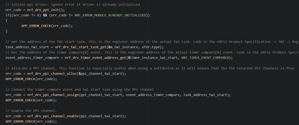
Use the PPI to link between Timer16 and TWI.
Get the TWI Handler callback and read the ArrayList content for X, Y axis computation.

Start the Timer16
Welcome to give any comment and feedback on this blog.

Just what I wanted. That’s great!
LikeLike
Good walk-thru, but a could you include the twi_config() code that was left out ? In my application I’m trying to set up EasyDMA to trigger on a gpiote event (external data ready signal), have it read over I2C a 24 bit value, and do that 10 times saving the values in sequential spots in a buffer. When done I’d like an interrupt to finally wake up the CPU so that I can process the data. I haven’t found examples that use the nrfx_twi* drivers. Got anything close ?
LikeLike
You can find more examples from https://github.com/Martinsbl/nrf5-mpu-examples. I have refer to get some ideas from it to do.
LikeLike
Hi This is Akhil. Can You sahte some examples with cst816 touch screen interfacing with nrf52840
LikeLike
Hi Jimmy,
I combine TWI with SPI, I got this :
nfo> app: Initializing disk 0 (SDC)…
rror> hardfault: HARD FAULT at 0x00000000
hardfault: R0: 0x20006E50 R1: 0x00000000 R2: 0x00000000 R3: 0x0
00000
rror> hardfault: R12: 0x20006E60 LR: 0x0004026B PSR: 0x40000013
hardfault: Cause: The processor has attempted to execute an instruction
at makes illegal use of the EPSR.
What issue do you reckon ?
LikeLike
I got it replace SPI0 to SPI1 in sdkconfig, thanks…:)
LikeLike