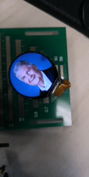
Following up to the blog LCD demo 320×240 @ nRF52840, I would like to describe how to use the QSPI interface to drive the bigger LCD display such as 360 x 360 resolution @ nRF52840.
QSPI Quad Serial Peripheral Interface
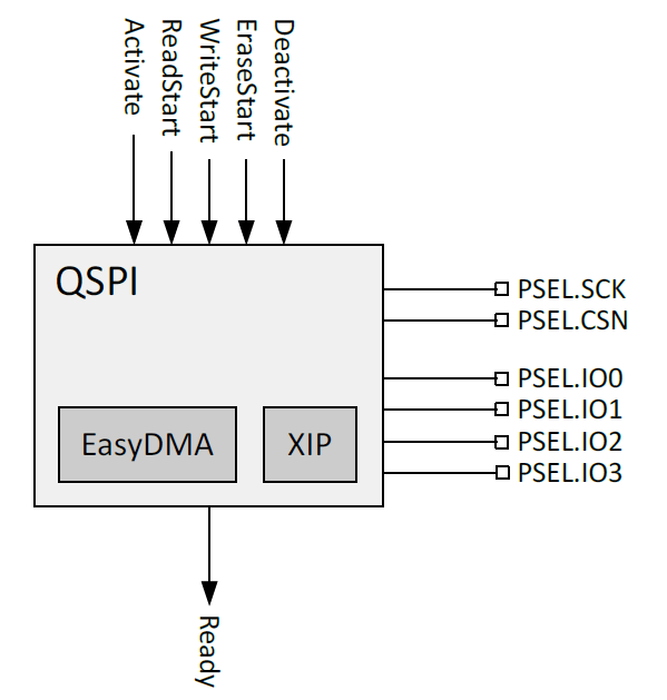
The QSPI peripheral provides support for communicating with an external flash memory device using SPI.
Listed here are the main features for the QSPI peripheral:
• Single/dual/quad SPI input/output
• 2–32 MHz configurable clock frequency
• Single-word read/write access from/to external flash
• EasyDMA for block read and write transfers
• Up to 16 MB/sec EasyDMA read rate
• Execute in place (XIP) for executing program directly from external flash
On the Nordic nRF52/nRF53 Series, the QSPI can support on two difference modes.
- Flash / XIP operation (It needs to follow the flash protocol)
- Sending Custom instructions (it limits to use the 1-wire on the QSPI for data sending).
On the instruction Set, it supports the Opcode with external flash device.

QSPI interface for the LCD
Basically, there are 6 GPIO pins for the QSPI interface.

In this blog, I would use the display manufacturer hannstar 360×360 with GalaxyCore Controller resolution for testing.
Initialize the QSPI Module
Configure all the 6 GPIO pins as the high drive output.
#define LCD_QSPI_RESET_PIN NRF_GPIO_PIN_MAP(0,27)
#define LCD_QSPI_CSN_PIN   NRF_GPIO_PIN_MAP(0,26)
#define LCD_QSPI_SCK_PIN   NRF_GPIO_PIN_MAP(0,02)
#define LCD_QSPI_IO0_PIN   NRF_GPIO_PIN_MAP(1,15)
#define LCD_QSPI_IO1_PIN   NRF_GPIO_PIN_MAP(1,14)
#define LCD_QSPI_IO2_PIN   NRF_GPIO_PIN_MAP(1,13)
#define LCD_QSPI_IO3_PIN   NRF_GPIO_PIN_MAP(1,12)

static void config_qspi_pin_high_drive(void)
{
        nrf_gpio_cfg(
                LCD_QSPI_SCK_PIN,
                NRF_GPIO_PIN_DIR_INPUT,
                NRF_GPIO_PIN_INPUT_CONNECT,
                NRF_GPIO_PIN_PULLDOWN,
                NRF_GPIO_PIN_H0H1,
                NRF_GPIO_PIN_SENSE_HIGH);
        nrf_gpio_cfg(
                LCD_QSPI_CSN_PIN,
                NRF_GPIO_PIN_DIR_INPUT,
                NRF_GPIO_PIN_INPUT_DISCONNECT,
                NRF_GPIO_PIN_NOPULL,
                NRF_GPIO_PIN_H0H1,
                NRF_GPIO_PIN_NOSENSE);

        nrf_gpio_cfg(
                LCD_QSPI_IO0_PIN,
                NRF_GPIO_PIN_DIR_INPUT,
                NRF_GPIO_PIN_INPUT_DISCONNECT,
                NRF_GPIO_PIN_PULLDOWN,
                NRF_GPIO_PIN_H0H1,
                NRF_GPIO_PIN_NOSENSE);

        nrf_gpio_cfg(
                LCD_QSPI_IO1_PIN,
                NRF_GPIO_PIN_DIR_INPUT,
                NRF_GPIO_PIN_INPUT_DISCONNECT,
                NRF_GPIO_PIN_PULLDOWN,
                NRF_GPIO_PIN_H0H1,
                NRF_GPIO_PIN_NOSENSE);

        nrf_gpio_cfg(
                LCD_QSPI_IO2_PIN,
                NRF_GPIO_PIN_DIR_INPUT,
                NRF_GPIO_PIN_INPUT_DISCONNECT,
                NRF_GPIO_PIN_PULLDOWN,
                NRF_GPIO_PIN_H0H1,
                NRF_GPIO_PIN_NOSENSE);

        nrf_gpio_cfg(
                LCD_QSPI_IO3_PIN,
                NRF_GPIO_PIN_DIR_INPUT,
                NRF_GPIO_PIN_INPUT_DISCONNECT,
                NRF_GPIO_PIN_PULLDOWN,
                NRF_GPIO_PIN_H0H1,
                NRF_GPIO_PIN_NOSENSE);
}
Initialize the QSPI module and configure it as 24 bits address/32MHz clock.
void qspi_lcd_GC9c01_init(void)
{
        if (!m_is_qspi_init)
        {
                uint32_t err_code;
                nrf_drv_qspi_config_t qspi_lcd_config = NRF_DRV_QSPI_DEFAULT_CONFIG;
                //config.phy_if.sck_freq  = NRF_QSPI_FREQ_32MDIV1;        //NRF_QSPI_FREQ_32MDIV8; //32MHz
                qspi_lcd_config.phy_if.sck_freq  = NRF_QSPI_FREQ_32MDIV1;        //NRF_QSPI_FREQ_32MDIV8; //32MHz
                //qspi_lcd_config.phy_if.sck_freq  = NRF_QSPI_FREQ_32MDIV8;//NRF_QSPI_FREQ_32MDIV8; //8MHz

                qspi_lcd_config.pins.csn_pin     = LCD_QSPI_CSN_PIN;
                qspi_lcd_config.pins.sck_pin     = LCD_QSPI_SCK_PIN;
                qspi_lcd_config.pins.io0_pin     = LCD_QSPI_IO0_PIN;
                qspi_lcd_config.pins.io1_pin     = LCD_QSPI_IO1_PIN;
                qspi_lcd_config.pins.io2_pin     = LCD_QSPI_IO2_PIN;
                qspi_lcd_config.pins.io3_pin     = LCD_QSPI_IO3_PIN;

                err_code = nrf_drv_qspi_init(&qspi_lcd_config, qspi_lcd_handler, NULL);
                APP_ERROR_CHECK(err_code);

                NRF_LOG_INFO("QSPI LCD Init");
                NRF_QSPI->IFCONFIG0 |= (QSPI_IFCONFIG0_PPSIZE_512Bytes << QSPI_IFCONFIG0_PPSIZE_Pos);

                m_is_qspi_init = true;
        }
        else
        {
                NRF_LOG_ERROR("QSPI LCD has already initialized!");
                APP_ERROR_CHECK(-1);
        }
}
Basically, there are 2 operations on the LCD.
- LCD Command Code (such as the LCD init code).
- LCD Data write (write the data on the LCD screen).
LCD Command Mode
LCD Write Command
static uint32_t drv_GC9c01_bus_writeCmd(const uint8_t cmd)
{
        return send_qspi_cinstr_w0d(cmd);
}

static uint32_t drv_GC9c01_bus_writeCmdByte(const uint8_t cmd, const uint8_t data)
{
        uint32_t err_code = NRF_SUCCESS;
        err_code  = send_qspi_cinstr_w1d(cmd, data);
        return err_code;
}
LCD initialize code
static void configure_lcd()
{
        drv_GC9c01_bus_writeCmd(0xfe);
        drv_GC9c01_bus_writeCmd(0xef);

        drv_GC9c01_bus_writeCmdByte(0x80, 0x11);
        drv_GC9c01_bus_writeCmdByte(0x81, 0x70);

        drv_GC9c01_bus_writeCmdByte(0x82, 0x09);
        drv_GC9c01_bus_writeCmdByte(0x83, 0x03);

        drv_GC9c01_bus_writeCmdByte(0x84, 0x20);
        drv_GC9c01_bus_writeCmdByte(0x85, 0x42);

        drv_GC9c01_bus_writeCmdByte(0x86, 0xfc);
        drv_GC9c01_bus_writeCmdByte(0x87, 0x09);

        drv_GC9c01_bus_writeCmdByte(0x89, 0x10);
        drv_GC9c01_bus_writeCmdByte(0x8a, 0x4f);

        drv_GC9c01_bus_writeCmdByte(0x8c, 0x59);
        drv_GC9c01_bus_writeCmdByte(0x8d, 0x51);

        drv_GC9c01_bus_writeCmdByte(0x8e, 0xae);
        drv_GC9c01_bus_writeCmdByte(0x8f, 0xf3);

        drv_GC9c01_bus_writeCmdByte(0x36, 0x00);
        drv_GC9c01_bus_writeCmdByte(0x3a, 0x05);
        drv_GC9c01_bus_writeCmdByte(0xec, 0x77);

        uint8_t parmater1_buffer[] = {0x01, 0x80, 0x00, 0x00, 0x00, 0x00};
        send_qspi_cinstr_long_frame_word(0x74, parmater1_buffer, 6);
        drv_GC9c01_bus_writeCmdByte(0x98, 0x3e);
        drv_GC9c01_bus_writeCmdByte(0x99, 0x3e);
        drv_GC9c01_bus_writeCmdByte(0xc3, 0x2A);
        drv_GC9c01_bus_writeCmdByte(0xc4, 0x18);
        send_qspi_cinstr_w1d_2data(0xa1,0x01,0x04);
        send_qspi_cinstr_w1d_2data(0xa2,0x01,0x04);
        drv_GC9c01_bus_writeCmdByte(0xa9, 0x1c);

        send_qspi_cinstr_w1d_2data(0xa5,0x11,0x09);
        drv_GC9c01_bus_writeCmdByte(0xb9, 0x8a);
        drv_GC9c01_bus_writeCmdByte(0xa8, 0x5e);
        drv_GC9c01_bus_writeCmdByte(0xa7, 0x40);
        drv_GC9c01_bus_writeCmdByte(0xaf, 0x73);
        drv_GC9c01_bus_writeCmdByte(0xae, 0x44);
        drv_GC9c01_bus_writeCmdByte(0xad, 0x38);

        drv_GC9c01_bus_writeCmdByte(0xa3, 0x5d);

        drv_GC9c01_bus_writeCmdByte(0xc2, 0x02);

        drv_GC9c01_bus_writeCmdByte(0xc5, 0x11);


        drv_GC9c01_bus_writeCmdByte(0xc6, 0x0e);

        drv_GC9c01_bus_writeCmdByte(0xc7, 0x13);
        drv_GC9c01_bus_writeCmdByte(0xc8, 0x0d);
        drv_GC9c01_bus_writeCmdByte(0xcb, 0x02);

        send_qspi_cinstr_w1d_2data(0x7c,0xb6,0x26);
        drv_GC9c01_bus_writeCmdByte(0xac, 0x24);
        drv_GC9c01_bus_writeCmdByte(0xf6, 0x80);


        send_qspi_cinstr_w1d_2data(0xb5,0x09,0x09);
        send_qspi_cinstr_w1d_4data(0x60, 0x38,0x0b,0x5b,0x56);
        send_qspi_cinstr_w1d_4data(0x63, 0x3a,0xe0,0x5b,0x56);

        uint8_t parmater2_buffer[] = {0x38, 0x0d, 0x72, 0xdd, 0x5b, 0x56};
        send_qspi_cinstr_long_frame_word(0x64, parmater2_buffer, 6);
        uint8_t parmater3_buffer[] = {0x38, 0x11, 0x72, 0xe1, 0x5b, 0x56};
        send_qspi_cinstr_long_frame_word(0x66, parmater3_buffer, 6);
        uint8_t parmater4_buffer[] = {0x3b, 0x08, 0x08, 0x00, 0x08, 0x29,0x5b};
        send_qspi_cinstr_long_frame_word(0x68, parmater4_buffer, 7);
        uint8_t parmater5_buffer[] = {0x00,0x00,0x00,0x07,0x01,0x13,0x11,0x0b, \
                                      0x09,0x16,0x15,0x1d,0x1e,0x00,0x00,0x00, \
                                      0x00,0x00,0x00,0x1e,0x1d,0x15,0x16,0x0a, \
                                      0x0c,0x12,0x14,0x02,0x08,0x00,0x00,0x00};
        send_qspi_cinstr_long_frame_word(0x6e, parmater5_buffer, 32);

        drv_GC9c01_bus_writeCmdByte(0xbe, 0x11);
        uint8_t parmater6_buffer[] = {0xcc, 0x0c, 0xcc, 0x84, 0xcc, 0x04,0x50};
        send_qspi_cinstr_long_frame_word(0x6c, parmater6_buffer, 7);
        drv_GC9c01_bus_writeCmdByte(0x7d, 0x72);
        drv_GC9c01_bus_writeCmdByte(0x7e, 0x38);
        uint8_t parmater7_buffer[] = {0x02,0x03,0x09,0x05,0x0c,0x06,0x09,0x05,0x0c,0x06};
        send_qspi_cinstr_long_frame_word(0x70, parmater7_buffer, 10);
        send_qspi_cinstr_w1d_4data(0x90, 0x06,0x06,0x05,0x06);
        send_qspi_cinstr_w1d_3data(0x93, 0x45,0xff,0x00);

        uint8_t parmater8_buffer[] = {0x45, 0x09, 0x08, 0x08, 0x26, 0x2a};
        send_qspi_cinstr_long_frame_word(0xf0, parmater8_buffer, 6);
        uint8_t parmater9_buffer[] = {0x43, 0x70, 0x72, 0x36, 0x37, 0x6f};
        send_qspi_cinstr_long_frame_word(0xf1, parmater9_buffer, 6);
        uint8_t parmater10_buffer[] = {0x45, 0x09, 0x08, 0x08, 0x26, 0x2a};
        send_qspi_cinstr_long_frame_word(0xf2, parmater10_buffer, 6);
        uint8_t parmater11_buffer[] = {0x43, 0x70, 0x72, 0x36, 0x37, 0x6f};
        send_qspi_cinstr_long_frame_word(0xf3, parmater11_buffer, 6);
        drv_GC9c01_bus_writeCmd(0xfe);
        drv_GC9c01_bus_writeCmd(0xee);


        // User Command Set (UCS = CMD1)------------------------------------------
        //       drv_GC9c01_bus_writeCmdByte(GC9c01_CMD_WRITE_CMD_MODE_PAGE, 0x00);

        //tearing effect line on--------------------------------------------------
        //       drv_GC9c01_bus_writeCmdByte(GC9c01_CMD_TEARING_EFFECT_ON, 0x00);

        // Interface Pixel Format-------------------------------------------------
        //       drv_GC9c01_bus_writeCmdByte(GC9c01_CMD_INTERFACE_PIXEL_FORMAT, 0x55);// 0x55 -> 565

        // Set_DSPI Mode----------------------------------------------------------
        //       drv_GC9c01_bus_writeCmdByte(GC9c01_CMD_SET_DSPI_MODE, 0x80);

        // Write display brightness-----------------------------------------------
        //GC9c01_drv_SetBrightness(0xCC);


        // Sleep-out and Display on-----------------------------------------------
        GC9c01_DRV_SLEEP_OUT();

        nrf_delay_ms(120);

        GC9c01_DRV_DISPLAY_ON();

        nrf_delay_ms(20);

        GC9c01_drv_setColRowPosition(0, 0);

        NRF_LOG_INFO("After %s", __func__);
}
Write LCD Data
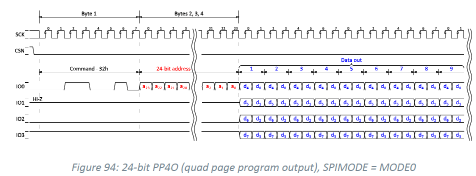
It uses the Opcode = 0x32 PP4O for the writing LCD data.
static uint32_t gc9c01_bus_lcd_write_buffer(uint8_t *p_tx_buffer, uint32_t len, uint32_t addr)
{
        uint32_t err_code = 0;
        m_finished = false;
        err_code = nrf_drv_qspi_write(p_tx_buffer, len, addr);
        if(err_code != NRFX_SUCCESS)
        {
                // NRF_LOG_INFO("error code= 0x%x",err_code);
        }
        WAIT_FOR_PERIPH();
        return err_code;
}

static void BMP_picture_show(uint32_t delay, const uint16_t *p_data)
{
        uint32_t err_code;
        uint32_t * p_color;
        uint32_t i,k;
        uint32_t tran_size,now_size=0;
        uint32_t remain_size = GC9c01_DRV_ALL_SIZE;

        //NRF_LOG_INFO("%s block_dx = %d, Color=%04x", __func__, a block_dx, color);
        //static uint8_t __ALIGN(4) bank_buf[QSPI_PAG_SIZE];

        tran_size = QSPI_PAG_SIZE;
        memcpy(&m_buffer_tx[0], (uint8_t *)&p_data[0]+tran_size, tran_size);
        err_code = gc9c01_bus_lcd_write_buffer(m_buffer_tx, QSPI_PAG_SIZE, 0x002C00);

        remain_size -= tran_size;
        now_size=tran_size;
        while (remain_size)
        {
                if (remain_size > QSPI_PAG_SIZE)
                {
                        tran_size = QSPI_PAG_SIZE;
                }
                else
                {
                        tran_size = remain_size;
                }

                memcpy(m_buffer_tx, (uint8_t *)&p_data[0]+now_size, tran_size);

                now_size += tran_size;
                err_code = gc9c01_bus_lcd_write_buffer(&m_buffer_tx[0], tran_size, 0x003C00);

                remain_size -= tran_size;
        }

        nrf_delay_ms(delay);
}

where did you find the dataheet for gc9c01 controller ? i have spent hours looking for it.. would you mind sharing it ? 🙂 I checked their website as well
LikeLike
You can try to contact their sale to get the datasheet. I can’t represent them to release the datasheet out.
LikeLike
Would you be willing to post all the project files on your git hub?
LikeLike
Would you be willing to post your project files on your github?
LikeLike
How were you able to activate QSPI ? When i hit the ACTIVATE_TASK , QSPI fires 05h read status command immediately and waits answer from the device hooked the peripheral .
So i check your LCD datasheet , it seems that LCD doesnt support 0x05 command … Maybe i am looking to the wrong datasheet . or you found a way to use QSPI without calling the ACTIVATE_TASK of it
LikeLike
I prefer you to use the logic analyzer to capture the communication trace on the QSPI.
And then you can see the datasheet how to write and read.
LikeLike
I did ,this is why I am curious , how you activated QSPI with or without TASK_ACTIVATE
LikeLike
Just write the data through QSPI interface and use the logic analyzer to check the data payload.
You should find the clue. I am not using the TASK and event in this case. Thus, I don’t use the TASK activate.
LikeLike
Thanks, much appreciate this helpful tutorial. Can you please share the snippets for following functions as well that are used in your code?
drv_GC9c01_bus_writeCmd
drv_GC9c01_bus_writeCmdByte
send_qspi_cinstr_long_frame_word
send_qspi_cinstr_w1d_2data
send_qspi_cinstr_w1d_3data
send_qspi_cinstr_w1d_4data
LikeLike
Thanks for great tutorial on QSPI driving the display. Could you please share the code snippet for these following functions:
1. send_qspi_cinstr_w0d(cmd);
2. send_qspi_cinstr_w1d(cmd, data);
3. send_qspi_cinstr_long_frame_word(0x66, parmater3_buffer, 6);
LikeLike
Thanks for great tutorial on QSPI driving the display. Could you please share the code snippet for these following functions:
1. send_qspi_cinstr_w0d(cmd);
2. send_qspi_cinstr_w1d(cmd, data);
3. send_qspi_cinstr_long_frame_word(0x66, parmater3_buffer, 6);
LikeLike
Thanks for the much needed tutorial. How do you set 0x32 instruction code for PP4O write? I set it in sdk_config.h but that doesn’t work. Can you also share the code snippets for following functions:
1. send_qspi_cinstr_long_frame_word()
2. send_qspi_cinstr_w0d
3. send_qspi_cinstr_w1d
LikeLike
Could you please send this project to my email?thank you
zxm@aishenlan.com
LikeLike
please send us project files to microbotxlabs@gmail.com please
LikeLike
I am unable to resolve the issue of incorrect data being displayed when driving the AMOLED display via QSPI.Would you please send this project to my email?jrryu1@gmail.com
LikeLike
I am unable to resolve the issue of incorrect data being displayed when driving the AMOLED display via QSPI.
Would you please send this project to my email?
jrryu1@gmail.com
LikeLike
I admire your knowledge.
Can you send me the project files?
vivazzanggu@naver.com
LikeLike
I am amazed by your knowledge.
Could you please share the source for this project?
vivazzanggu@naver.com
LikeLike
You really have the right card in this work. I would be grateful if you could email me the project file.my email : ghanbariparsa2016@gmail.com
LikeLike