In this blog, I would like to introduce the method how to test on the RF (Radio) on the NRF5 Series.
It would covers the following topics.
- nRF Connect RSSI Viewer
- Simple Radio Test
- Direct Test Mode
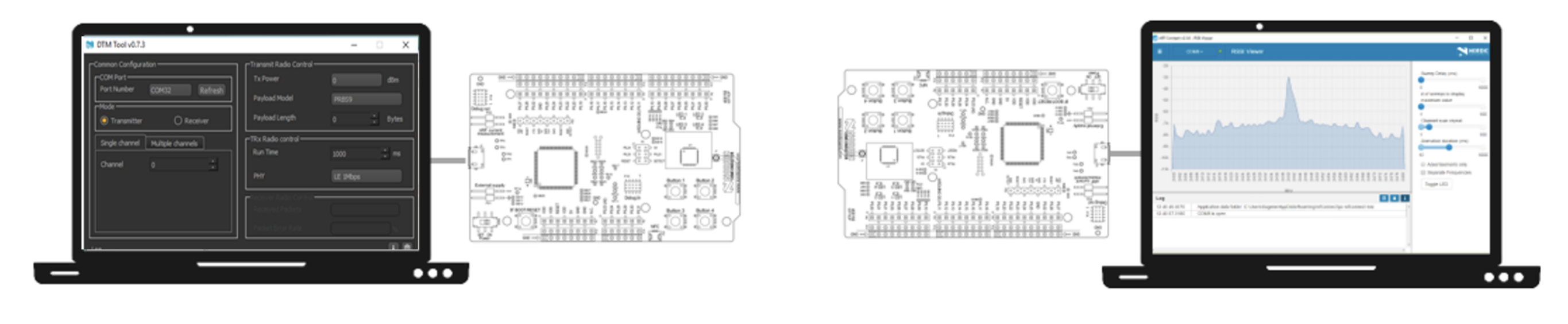
nRF Connect RSSI Viewer
Simple app for nRF Connect that shows a visualization of RSSI data. The app shows dBm per frequency in the 2400-2480 MHz range, and allows the user to tweak settings like sweep delay and animation duration. The app can be installed from the Add/remove apps screen in nRF Connect.
The following devices are supported:
- PCA10040 nRF52832 Development Kit
- PCA10059 nRF52840 Dongle
https://github.com/NordicSemiconductor/pc-nrfconnect-rssi

Radio Test Example
The Radio Test Example demonstrates how to configure the radio as the constant RX or TX carrier, the modulated TX carrier, or the RX or TX sweep.
The tests are controlled with Command Line Interface (CLI) by the serial port. At any time during the tests, you can set the radio parameters output power, bit rate, and channel. You can also set the time on each channel in the sweep mode, in steps of 1 millisecond to 99 milliseconds, every 1 millisecond. The application also allows you to send a data pattern to another board.
The application starts with enabling the high frequency crystal oscillator and configuring CLI. Calling a console command causes the appropriate action.
CLI commands
The following table lists the available main CLI commands, in alphabetical order.
| Command | Argument | Description |
|---|---|---|
cancel | Cancel the sweep or the carrier. | |
data_rate | <sub_cmd> | Set the data rate. |
end_channel | <channel> | End the channel for the sweep. |
output_power | <sub_cmd> | Output power set. |
parameters_print | Print current delay, channel, and other parameters. | |
print_rx | Print the received RX payload. | |
start_channel | <channel> | Start the channel for the sweep or the channel for the constant carrier. |
start_duty_cycle_modulated_tx | <duty_cycle> | Duty cycle in percent (two decimal digits, between 01 and 99). |
start_rx | Start RX. | |
start_rx_sweep | Start the RX sweep. | |
start_tx_carrier | Start the TX carrier. | |
start_tx_modulated_carrier | Start the modulated TX carrier. | |
start_tx_sweep | Start the TX sweep. | |
time_on_channel | <time> | Time on each channel (between 1 ms and 99 ms). |
toggle_dcdc_state | <state> | Toggle DC/DC converter state. |
transmit_pattern | <sub_cmd> | Set transmission pattern. |
You can find the source code and the project file of the example in the following folder: <InstallFolder>\examples\peripheral\radio_test
Direct Test Mode (DTM)
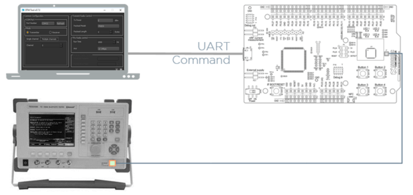
The main function of a production test is to verify that all the components are mounted correctly and have correct values after assembling a device. To perform a production test on a Bluetooth® low energy application, it is preferable to use a builtin function called Direct Test Mode (DTM). The DTM enables testing of the RF parameters and is also used for end-product qualification testing of the RF physical layer (RF PHY). Bluetooth low energy products of Nordic include a UART interface that gives access to the Direct Test Mode (DTM).
The DTM has two main modes of operation; the transmit test mode and the receive test mode. In transmit test mode, the Device Under Test (DUT) generates a predefined set of test packets. In receive test mode, the DUT counts the number of test packets received.

The DTM is specified on the bluetooth core specification (available from this site) in Vol 6, Part F.
In addition, you can have a look at the python scripts that implements DTM from bluetooth v4.0 in nAN-34:
nAN34 – Setting up production test using DTM
DTM enables a set of RF PHY test cases, which are defined by the Bluetooth Special Interest Group (SIG) in the documents from the sections called “TCRL Release Table” and “Core – Test Requirements for v4.0 or later” found at the beginning of the https://www.bluetooth.com/specifications/qualification-test-requirements web page.
Note: The following information was updated in the first half of 2017. For current information, refer to the newer TCRL 2017-1, that is, to the corresponding 2017-1 TCRLs-1.zip file containing the newer RF-PHY.TS.5.0.1.
The Capability tests (as defined in the standard ISO subgroups) are organized in levels and groups representing protocol services, functional modules, and purposes, the latter being divided in operating conditions for the transmitter and the receiver. All the relevant RF PHY tests are in accordance to the test specifications RF-PHY.TS.4.2.3 or the updated RF-PHY.TS.5.0.0 and are shown in the RFPHY sheet of the Excel file called Core.TCRL.2016-2.xlsx found inside the 2016-2 TCRLs.zip.
Below are examples of test cases for the Physical Layer Conformance. They are referred to by their identifiers, where TP stands for
Test Purpose and TRM-LE and RCV-LE stand for LE Transmitter and LE Receiver test respectively.
• TP/TRM-LE/CA/BV-01-C [Maximum peak and average output power]
• TP/TRM-LE/CA/BV-03-C [In-band spectral emissions]
• TP/TRM-LE/CA/BV-05-C [Modulation Characteristics]
• TP/TRM-LE/CA/BV-06-C [Carrier frequency offset and carrier drift]
• TP/RCV-LE/CA/BV-01-C [Receiver sensitivity]
• TP/RCV-LE/CA/BV-03-C [C/I and Receiver Selectivity Performance] [Additional blocker needed to generate co-/adjacent channel interference]
• TP/RCV-LE/CA/BV-04-C [Blocking Performance] [Additional blocker needed to generate interference outside the 2400MHz –
2483.5MHz band]
• TP/RCV-LE/CA/BV-05-C [Intermodulation Performance] [2 x additional blocker needed to generate both a sinusoidal/un-modulated
and a continuous/modulated carrier]
• TP/RCV-LE/CA/BV-06-C [Maximum input signal level]
• TP/RCV-LE/CA/BV-07-C [PER Report Integrity]
Additional test cases have been introduced since the release of Bluetooth 5. A few examples of the many new test cases are listed
below:
• TP/TRM-LE/CA/BV-08-C [In-band emissions at 2 Ms/s]
• TP/TRM-LE/CA/BV-10-C [Modulation Characteristics at 2 Ms/s]
• TP/RCV-LE/CA/BV-08-C [Receiver sensitivity at 2 Ms/s]
• TP/RCV-LE/CA/BV-10-C [Blocking performance at 2 Ms/s]
Two Wire Commands through DTM
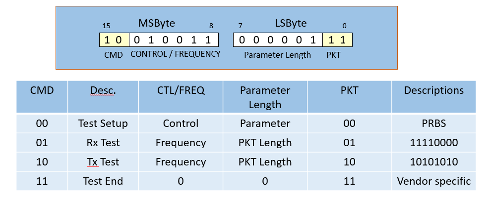
Command Packet
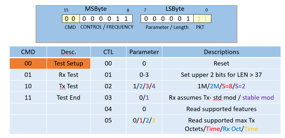
Command packet test setup
Command Packet – TX / RX (and Nordic Vendor Specify)
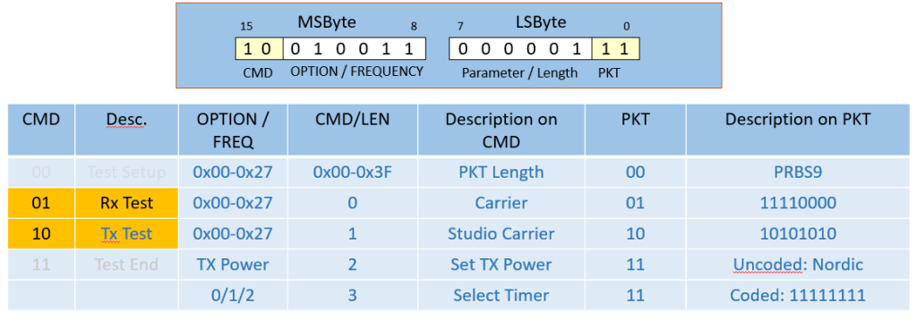
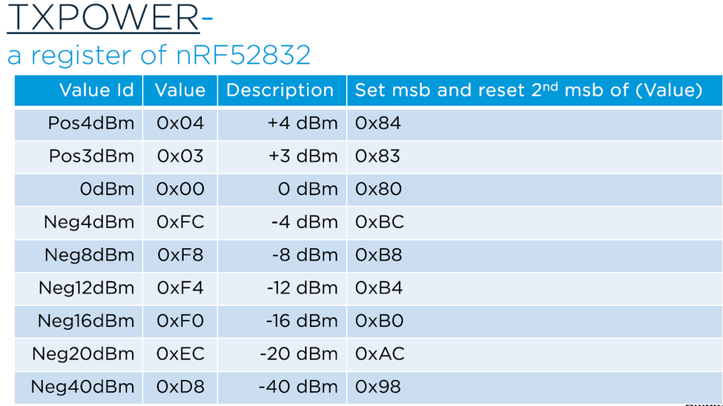
TX Power on NRF52832
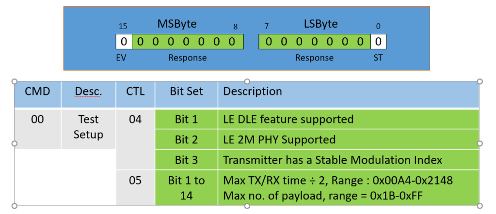
2-Wire Event Packet

Test Status Response
Example command on the UART for DTM
Basic commands
- RESET: 0x00 0x00
- TEST END: 0xC0 0x00
Transmit test
- Channel 0, i.e. 2402MHz pure carrier
- 0x00 0x00 0x80 0x07
- Channel 19, i.e. 2440MHz 10 byte PRBS9 payload
- 0x00 0x00 0x93 0x28
The above commands will send packets until TEST END is received
To sweep channels, make a loop of RF channel increment.
Receive test
- Channel 19, i.e. 2440MHz
- 0x00 0x00 0x53 0x00
The above command receives all types of payload continuously until TEST END command is received.
Bluetooth 5 Example (DTM)
Nordic Specific
Basic commands
- RESET: 0x00 0x00
- TEST END: 0xC0 0x00
Transmit Test:
Channel 19, i.e. 2440MHz 10 bytes PRBS9 payload
- 0x00 0x00 0x09 0x28
Set TX Power +4dBm
- 0x84 0x0B
Channel 0 i.e. 2402MHz carrier
- 0x80 0x03
Channel 19 37bytes PRBS9 payload
- 0x93 0x94
Check feature supported
- 0x04 0x00
Set 2Mbps mode
- 0x93 0x94
Receive test:
Channel 19, i.e. 2440MHz
- 0x00 0x00 0x53 0x000
If you need to get the tool on PC for DTM, you can download it from https://github.com/olleheugene/nRF-DTM.

The nRF_DTM is UI based test tool that helping to RF test by easy control
- UI based RF test tool
- Support Bluetooth 5 features (2Mbps/Coded S8/Coded S2/1Mbps)
- Support 3 Different channels testing (High/Mid/Low)
- Configurable Tx Power
- Support PER measurement
- Support configurable log level in order to check test sequence and detiails
- Support direct command on terminal and command line interface on shell
Thanks for your interests on my blog. Since 2019, I have created this blog and shared the idea how to do some funny stuffs. I am very pleasure that I get quite a lot of positive feedback. I really hope that this blog helps your own embedded solution development. May I get support from you to keep it in order to maintain the wordpress host service? Your appreciation would be very helpful.
https://jimmywongiot.com/2021/05/26/asking-for-support/


Thanks for finally writing about > RF Physical Test on the nRF5 Series –
jimmywongiot < Loved it!
LikeLike
Thanks for finally writing about > RF Physical Test on the nRF5 Series – jimmywongiot < Liked it!
LikeLike
Thank you for sharing your thoughts. I truly appreciate your efforts and I will be waiting for
your further write ups thank you once again.
LikeLike
It is not my first time to go to see this website, i am browsing this site dailly and obtain good information from here all the time.
LikeLike
Hi there, the whole thing is going perfectly here and ofcourse every one is sharing facts, that’s genuinely good, keep
up writing.
LikeLike
Hi there! I’m at work surfing around your blog from my new iphone 4!
Just wanted to say I love reading your blog and look forward to all your
posts! Keep up the excellent work!
LikeLike
Hi Jimmy! Thank you for the awesome write-up and the nRF-DTM PC utility.
I tested with nrf51822 controller (onboard PA / LNA) that I have, I am facing an issue when I put the transmitter in Constant Carrier mode then PER is 100% on the receiver but for other Payload models it is working fine. What could be the issue?
PS: It work for me couple of times and then stopped all of a sudden.
Thanks in advance for your help.
LikeLike
Hi Jimmy! Thank your for the awesome blog and nRF-DTM software for PC.
I tested this with nRF51822 controller (with onboard PA/ LNA) that I have. All the Payload models are working fine except for Constant Carrier, with Constant Carrier the PER is 100% on the receiver end. Any pointers on what could be the issue?
Thanks for your help in advance.
LikeLike
Hi,
If you are using constant carrier, it means that the radio packet doesnt consist of any data ‘0’ or ‘1’. PER is 100%. This is in expectation.
LikeLike
Noted! Thanks for quick response.
There is one more thing, I am getting “ERROR> (Set Tx power) Event Error” whenever I set Tx power to negative value (-4dBm or lower).
LikeLike
I can’t get your question clearly. You may get some helps on the nordic devzone and describe your question clearly.
LikeLike
I got it sorted, made a mistake while building the firmware. Thanks for your help!
LikeLike
Have you ever considered about adding a little bit more than just your articles?
I mean, what you say is fundamental and everything. Nevertheless think of if you
added some great pictures or videos to give your posts more, “pop”!
Your content is excellent but with images and clips,
this website could certainly be one of the very best in its field.
Very good blog!
LikeLike
Hello! I could have sworn I’ve been to your blog before but after looking at some of the posts
I realized it’s new to me. Regardless, I’m certainly happy I discovered it and I’ll be book-marking it and
checking back regularly!
LikeLike
Awesome article.
LikeLike
Hey there! I’ve been following your web site for a long time now and finally got the courage to go
ahead and give you a shout out from Houston Tx! Just wanted to say keep up the great job!
LikeLike
Quality posts is the key to interest the users to pay a quick visit the site,
that’s what this web page is providing.
LikeLike
Very good write-up. I certainly love this site.
Keep it up!
LikeLike
I was able to find good information from your content.
LikeLike
Hi there, yes this piece of writing is actually good and I have learned lot of things from it regarding blogging.
thanks.
LikeLike
hi ,
i m testing my nrf52832 by dtm.
I m flashing dtm code with rx tx pin changes.
By using DTM tool. i transmit the signal.
i m getting exactly what u have posted in gif.But in lab, they said not getting any signal.
I dont know what is the issue ?
kindly help me
LikeLike
You can use extra board as the golden unit to receive the data . It can help you to verify what problem you have.
LikeLike
thanks for quick reply
I tested two boards (one is transmitter and other one is receiver)in my office . I can able to receive packets which same as your gif.
But in the lab ,they said not receiving signal from the board.
LikeLike