In this blog, I would like to show an example how to count the number of raising / falling edge on particular GPIO pin without running the MCU.
For example, we need to count how many pulse from the MCU through GPIO.
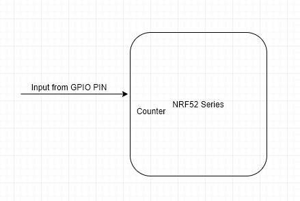
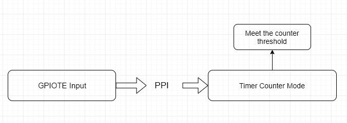
By using the GPIOTE and Timer Counter Mode through PPI, it can count without the MCU involve.
GPIOTE — GPIO tasks and events
The GPIO tasks and events (GPIOTE) module provides functionality for accessing GPIO pins using tasks and events. Each GPIOTE channel can be assigned to one pin.
A GPIOTE block enables GPIOs to generate events on pin state change which can be used to carry out tasks through the PPI system. A GPIO can also be driven to change state on system events using the PPI system. Low power detection of pin state changes is possible when in System ON or System OFF.
Up to three tasks can be used in each GPIOTE channel for performing write operations to a pin. Two tasks are fixed (SET and CLR), and one (OUT) is configurable to perform following operations:
- Set
- Clear
- Toggle
An event can be generated in each GPIOTE channel from one of the following input conditions:
- Rising edge
- Falling edge
- Any change
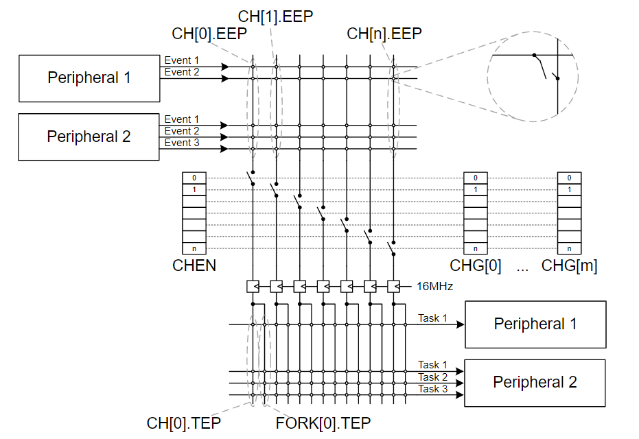
PPI — Programmable peripheral interconnect
The PPI allows precise synchronization between peripherals when real-time application constraints exist and eliminates the need for CPU activity to implement behavior which can be predefined using PPI.
IRQ vs Programmable Peripheral Interconnect (PPI)
It can save the current consumption without wake up the MCU.

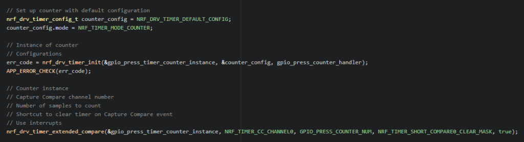
Initialize the Timer
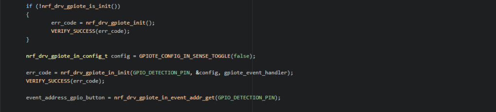
GPIOTE initialization
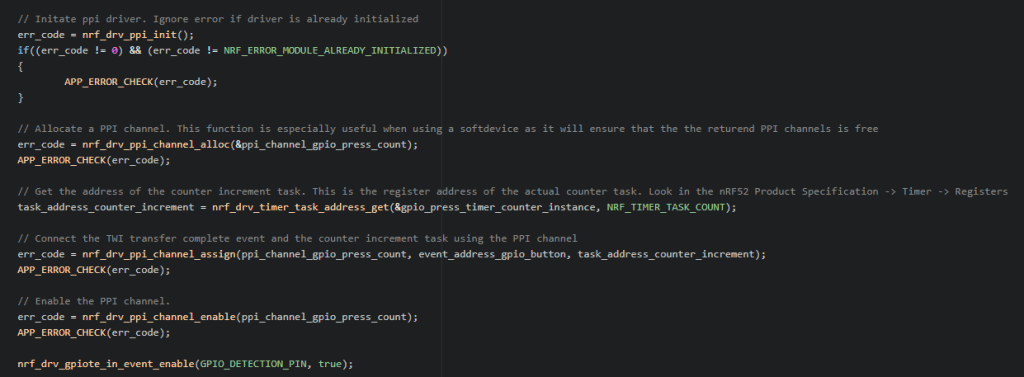
Programmable Peripheral Interconnect
The example code is located at https://github.com/jimmywong2003/nrf5-gpio-ppi-timer-counter.
