In this blog, I would describe the UICR region and how to use it in details.
It covers the following topic:
- Memory Layout (Address) of the UICR
- Registers in UICR (and each functionality)
- How to write / read / erase on the UICR by using the nrfjprog
- Dump flash / ram / registers
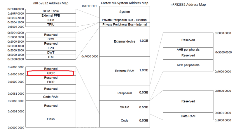
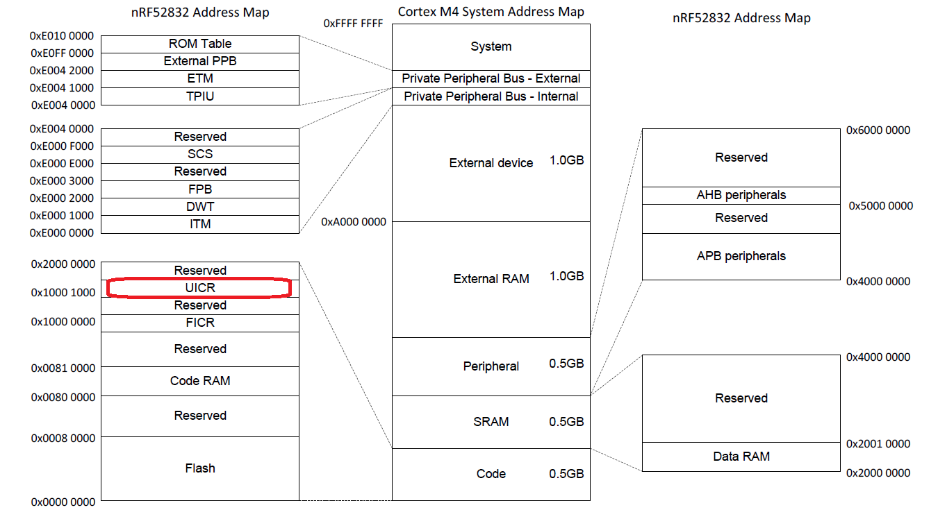
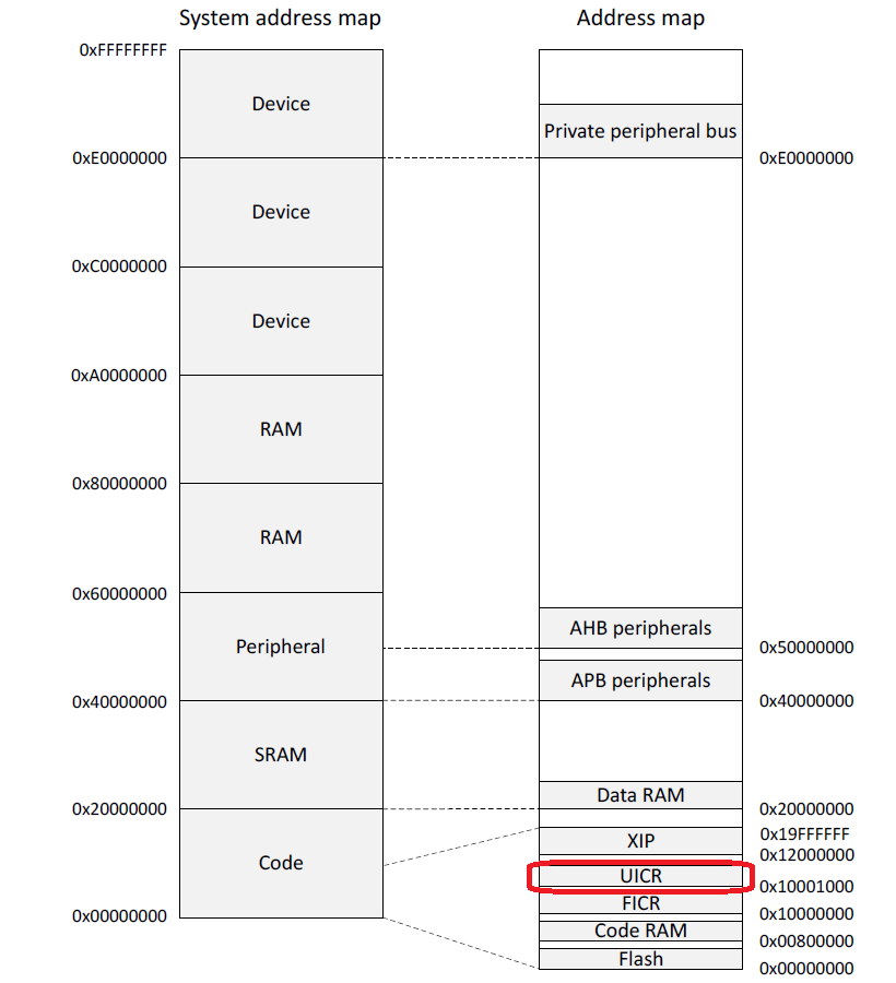
Memory Layout
The user information configuration registers (UICRs) are non-volatile memory (NVM) registers for configuring
user specific settings.
Registers in UICR (and each functionality)
| Region of UICR | Register | Description |
| 0x00 – 0x14 | Reserved | |
| 0x14 – 0x80 | NRFFW[0] – NRFHW[14] | Reserved for Nordic Firmware Design |
| 0x50 – 0x80 | NRFHW[0] – NRFHW[11] | Reserved for Nordic Firmware Design |
| 0x80 – 0x100 | CUSTOMER[0] – CUSTOMER[31] | Reserved for customer |
| 0x200 | PSELRESET[0] | Mapping of the nRESET function |
| 0x204 | PSELRESET[1] | Mapping of the nRESET function |
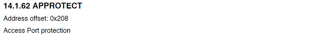
| 0x208 | APPROTECT | Access Port protection |
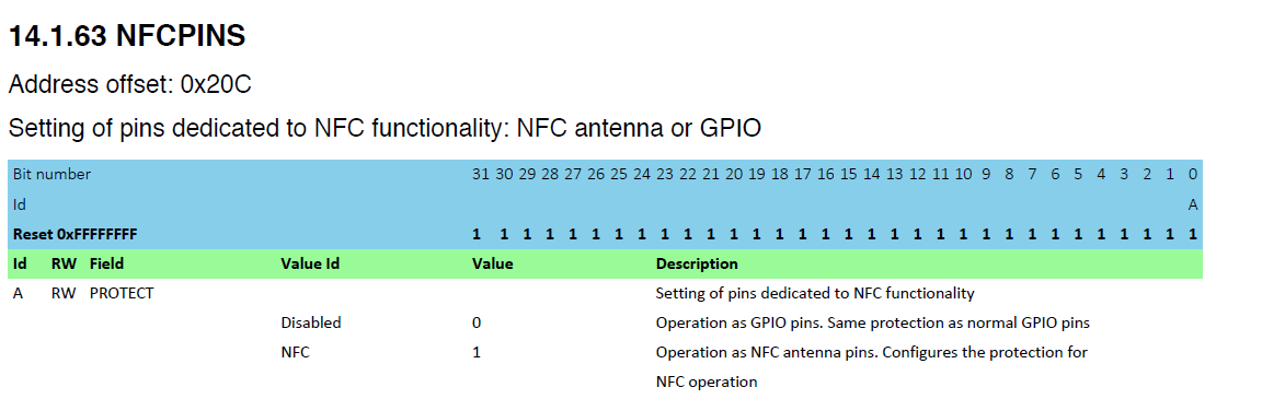
| 0x20C | NFCPINS | Setting of pins dedicated to NFC functionality: NFC antenna or GPIO |
| 0x210 | DEBUGCTRL (nRF52840 only) | Processor debug control |
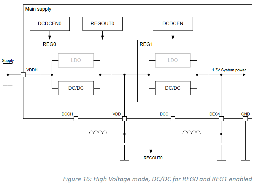
| 0x304 | REGOUT0 (nRF52840 only) | GPIO reference voltage / external output supply voltage in high voltage mode |
https://devzone.nordicsemi.com/f/nordic-q-a/18257/how-to-write-data-to-uicr-customer-registers
Reference Schematic of nRF52832 QFAA

P.021 is used for the HW Reset Pin or GPIO.
It is configured by the UICR Register (PSELRESET[0] and PSELRESET[1]).
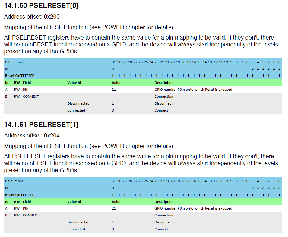
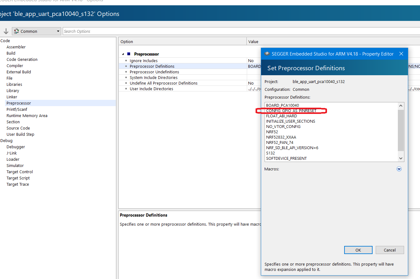
In the SDK, compile switch (CONFIG_GPIO_AS_PINRESET) is used for this.
Access Port protection
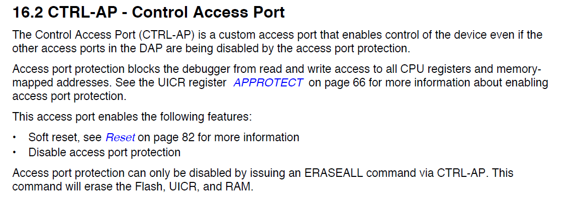
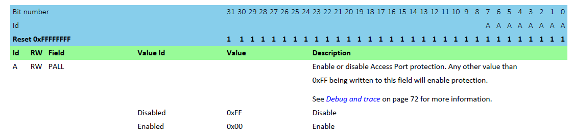
If the UICR register APPPROTECT is set to 0xFF (default disable), the AHB-AP is connected to the debugger bus. Otherwise, it is disconnected (APPPROTECT = 0x00).
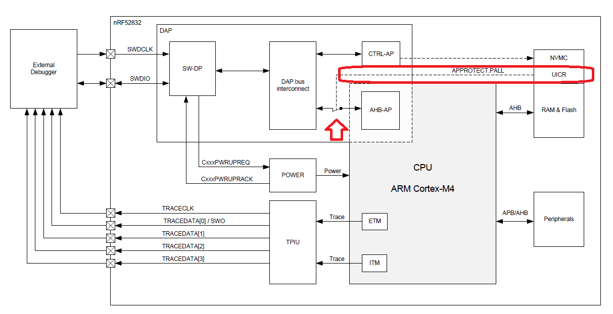
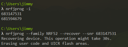
If you would like to recover (after enabling the APPPROTECT), there are 3 different approaches.
- Use nrfjprog.exe -f NRF52 –recover
- Use nrfjprog.dll function recover() or use the pynrfjprog recover()
- Manually, a) write 1 to register 0x4 of debug access port 1, b) read register 0x8 of debug access port until its value is 0, c) write 0 to register 0x4 of debug access port 1, d) write 1 to register 0x0 of debug access port 1, e) write 0 to register 0 of debug access port 1.
NFC on the NRF52832 / NRF52840
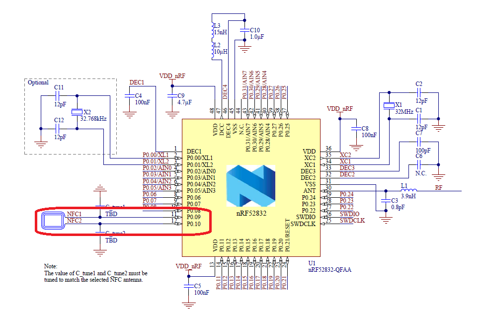
GPIO 9 / 10 can be used for the NFC tag.
By configuring the UICR Register NFCPINS as below.
Debug control (nRF52840 only), It is used for advanced PCU debug feature and flash patch.
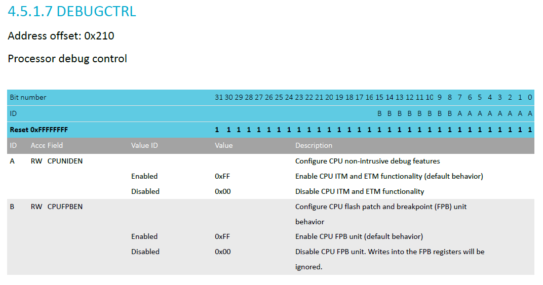
- ETM(Embedded Trace Macrocell)
- ITM(Instrumentation Trace Macrocell)
ITM means you can create a debug channel for sending messages from your code to the debugger.
ETM means that the chip hardware can stream out step-by-step how it walks through the instruction stream. There is heavy data compression involved so it basically just informs the debugger with “y”, “n”, “n”, “y” if it takes jumps or not.
This means the debugger on the PC can recreate a virtual copy of the instruction sequence the processor performs.
So you can look back in time and evaluate the instruction sequence that led the program into a specific state.
This is a big advantage if you need to solve issues with magically hanging software, programs making unexpected jumps, getting stuck in interrupt service routines etc.
So ETM is very good when your program performs unexpected crash-and-burn magic.
And ITM is good for getting some trace output of the performance of your business logic “config saved”, “motor started”, “user intervention timeout”, …
You pay extra for a ULINKpro just because it gives an additional professional feature intending to cut down debug times when something is really off and you can’t just rely on single-stepping through the program. Single-stepping doesn’t work well in a real-time system where the external hardware doesn’t stop the time just because you want to stop the time in the debugger.
So ETM is in some ways a flight data recorder (black box) crash protected memory. Expensive but valuable.
Regulator OUT 0 (nRF52840 only)

How to write / read / erase on the UICR by using the nrfjprog
nRF5x Command Line Tools
The nRF5x Command Line Tools are used for developing, programming, and debugging of Nordic Semiconductor’s nRF5x SoCs (System on Chip).
The nRF5x Command Line Tools consist of the following components:
- nrfjprog executable: The nrfjprog executable is a command line tool for programming nRF5x Series SoCs through SEGGER J-Link programmers and debuggers.
- mergehex executable: The mergehex executable is a command line utility that enables you to combine up to three HEX files into a single file.
- nrfjprog DLL: The nrfjprog DLL is a Dynamic-Link Library that exports functions for programming and controlling Nordic Semiconductor nRF5x Series SoCs. It lets developers create their own development tools for Nordic Semiconductor nRF5x SoCs using the DLLs API.
- SEGGER J-Link software and documentation pack (included only in the Windows installer).
Nordic provides the command line (nRF Command line tool) to configure the nRF5 / nRF91 Series. The user manual is located at https://infocenter.nordicsemi.com/pdf/nRF5x_Command_Line_Tools_v1.0.pdf .
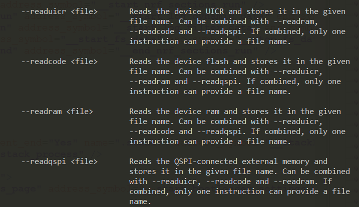
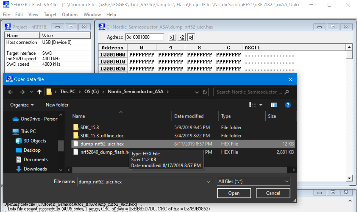
Dump the hex from the device
- Dump entire flash such as 512KB flash from nRF52832
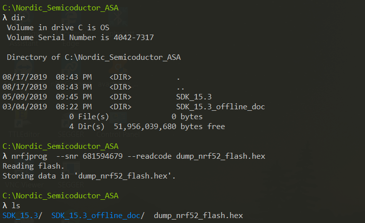
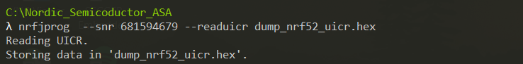
- Dump the UICR region from nRF52
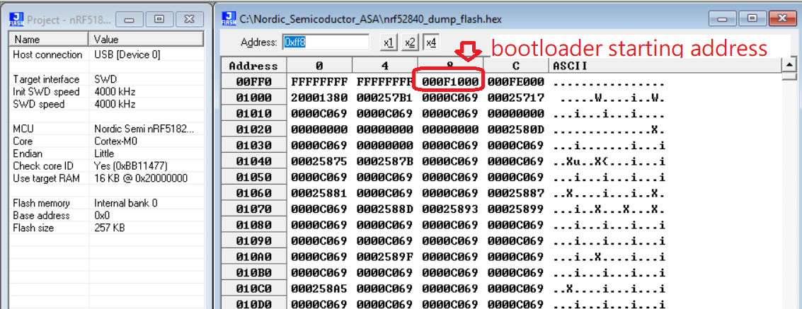
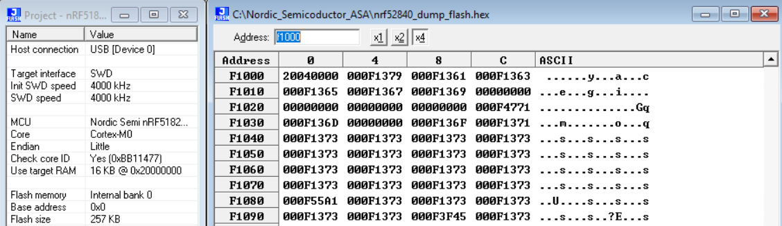
The hex file can be viewed by J-Flash tool as below,
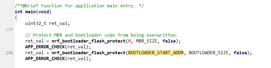
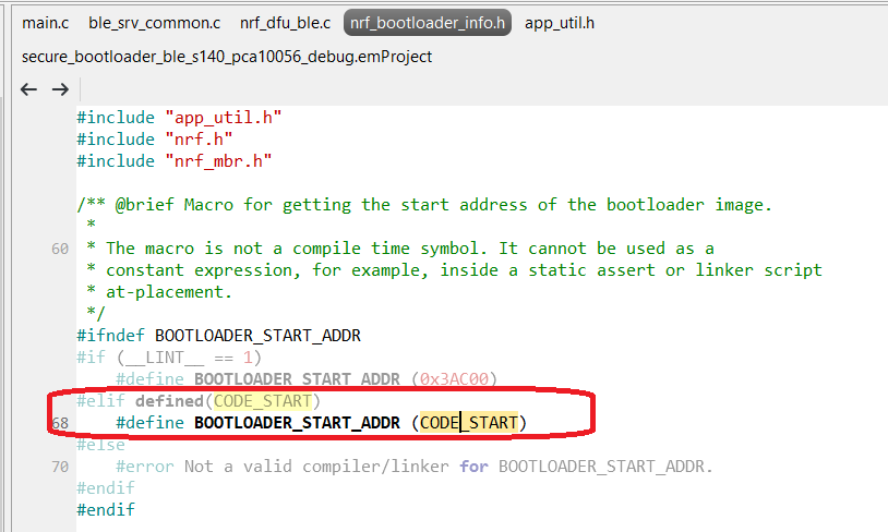
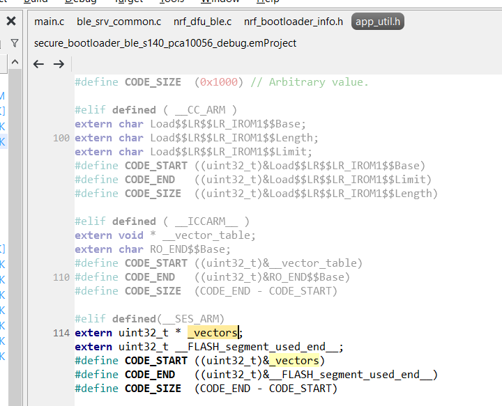
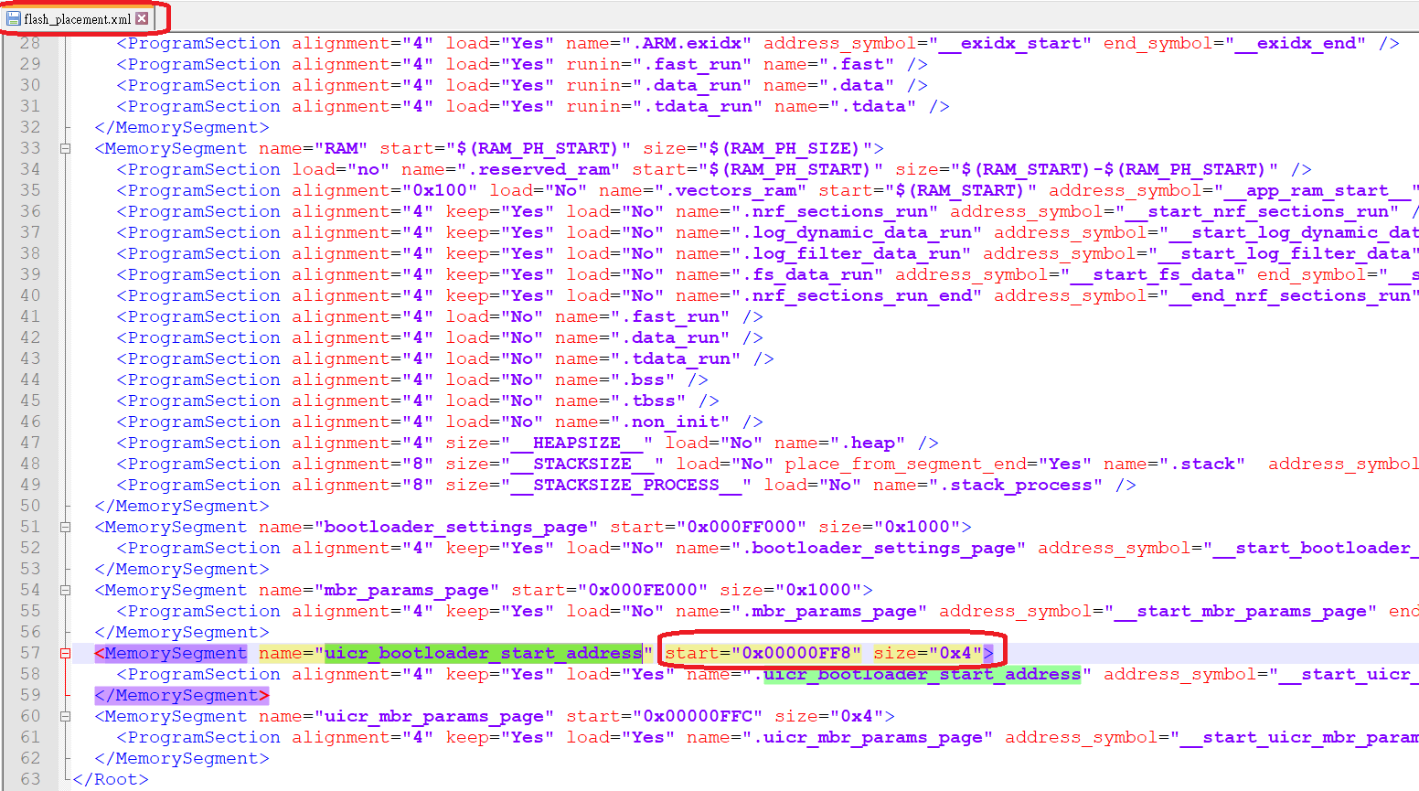
Bootloader Starting address (difference from OLD SDK). It is not stored at the UICR 0x10001014.
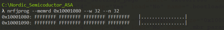
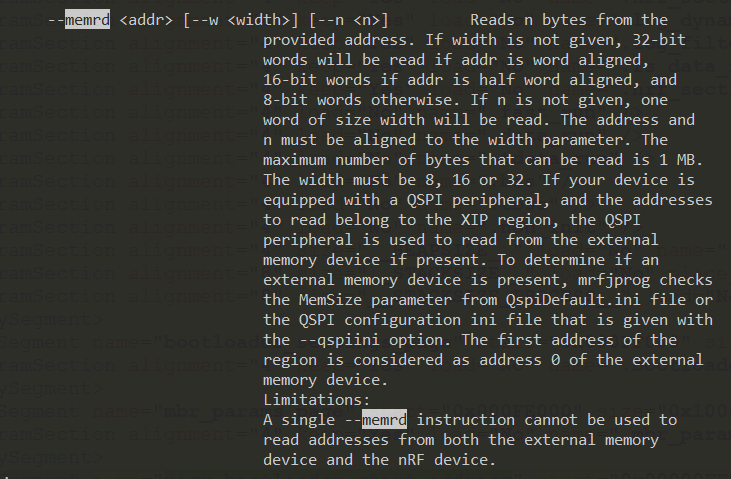
Read the specify address through nrfjprog tool
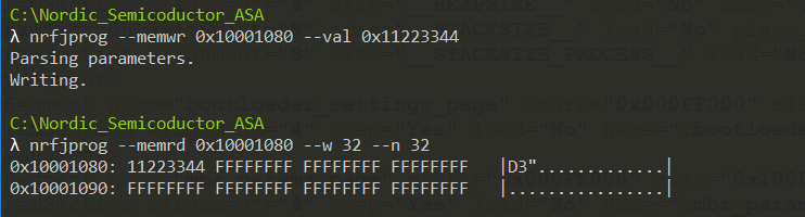
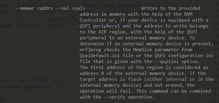
Write data on the address through nrfjprog
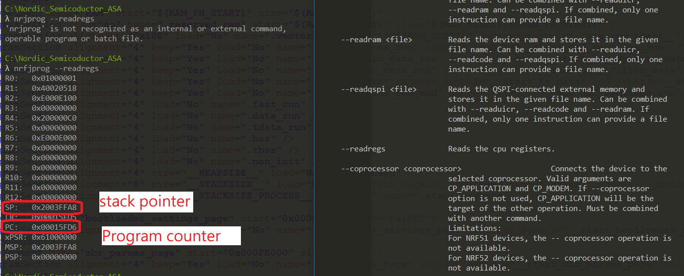
Read the registers
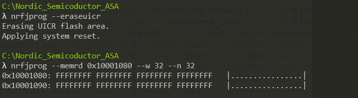
Erase the UICR region
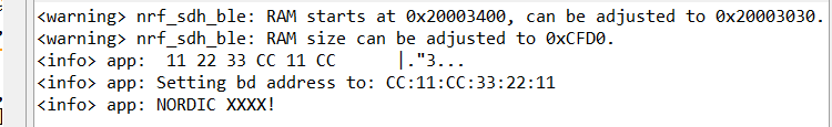
Change the MAC address on nRF52 and store it inside the UICR region
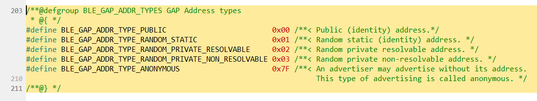
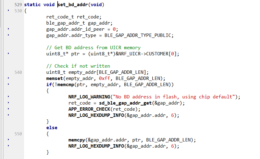
Example code to get / set the MAC address (remember to set the address type also)
void get_MAC_address_with_HEX(char * str_MAC)
{
    ble_gap_addr_t		addr;
    uint32_t err_code = sd_ble_gap_addr_get( &addr);
    APP_ERROR_CHECK(err_code);

    sprintf(str_MAC,"%02X%02X%02X%02X%02X%02X", \
    addr.addr[5],addr.addr[4],addr.addr[3],addr.addr[2],addr.addr[1],addr.addr[0]);

    NRF_LOG_INFO("MAC ADDRESS: %02X,%02X,%02X,%02X,%02X,%02X!", \
    addr.addr[0],addr.addr[1],addr.addr[2],addr.addr[3],addr.addr[4],addr.addr[5]);
}

void change_MAC_address( ble_gap_addr_t	addr)
{
    addr.addr_type = BLE_GAP_ADDR_TYPE_PUBLIC;
    uint32_t err_code = sd_ble_gap_addr_set( &addr );
    APP_ERROR_CHECK(err_code);
}
for example,
Register Location
The 6-byte BLE Radio MAC address is stored in the nRF51822 UICR at NRF_UICR_BASE+0x80 LSB first.
NRF_UICR + 0x80 (0x10001080): MAC_Addr [0] (0xC0)
NRF_UICR + 0x81 (0x10001081): MAC_Addr [1] (0xYY)
NRF_UICR + 0x82 (0x10001082): MAC_Addr [2] (0xXX)
NRF_UICR + 0x83 (0x10001083): MAC_Addr [3] (0x93)
NRF_UICR + 0x84 (0x10001084): MAC_Addr [4] (0x54)
NRF_UICR + 0x85 (0x10001085): MAC_Addr [5] (0xDD)
Using the MAC address
To have the radio use this stored MAC address you need to read it from the UICR and pass the address to
sd_ble_gap_addr_set();
If you do not call sd_ble_gap_addr_set(), the radio will use a random public MAC address, stored in the FICR. Please refer to Nordic’s SoftDevice documentation and SDK regarding the use of the sd_ble_gap_addr_set() function.
Reprogramming the MAC address
Use a J-Link interface with the savebin and loadbin commands. These can be included in a script.
- //save the MAC from UICR + 0x80
savebin mac_addr.bin 0x10001080 8 // memory reads must be in 4-byte increments - //restore the MAC from the file and program to UICR + 0x80
loadbin mac_addr.bin 0x10001080
Here are the code as example

If you like this blog, would you give me a “like” for appreciation?
Thanks for your interests on my blog. Since 2019, I have created this blog and shared the idea how to do some funny stuffs. I am very pleasure that I get quite a lot of positive feedback. I really hope that this blog helps your own embedded solution development. May I get support from you to keep it in order to maintain the wordpress host service? Your appreciation would be very helpful.
https://jimmywongiot.com/2021/05/26/asking-for-support/

