
Situation
From cheap toys, mobile accessory, medical device and home automatic electronic systems, printed circuit boards (PCB) are critical components for today’s electronic and industrial technology. Almost every electronic device has one of these self-contained modules of complex interconnected electronic components, which include resistors, capacitors, transistors, diodes and fuses.
Printed circuit boards can cover a single task or multiple functions. PCBs come in three major types:
- Single-sided
- Double-sided
- Multilayer
During mass production stage, PCB soldering issues are one of the common / critical problem.
For example, some blogs would mention top 10 PCB soldering issues. (https://www.autodesk.com/products/eagle/blog/top-10-soldering-issues-can-ruin-pcb-design/)
Goals
In this blog, I propose a method (running JLINK script) to check all the GPIO pins status in order to fast analyze whether the failure board is caused by soldering or not.
The idea is to configure the GPIO I/O pin as output pin and set to high value. The output result would be recorded. After running multiple boards (including good and bad units), it would get multiple result.
By comparing those results, it would be easy to figure out which board has difference result. It implies that the difference may be caused by the soldering issues.
Requirements
- Windows, macOS, Linux PC
- JLInk (https://www.segger.com/downloads/jlink/)
- microUSB cable
Method
The method is to run the JLINK Script on the good and bad units, and then do the comparison which GPIO pins output are difference.

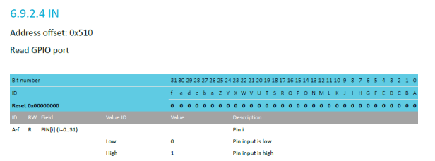
This is the GPIO IN register on the NRF52840.
All the materials can be found at https://github.com/jimmywong2003/nrf5-check-gpio-jlink-script-test.
