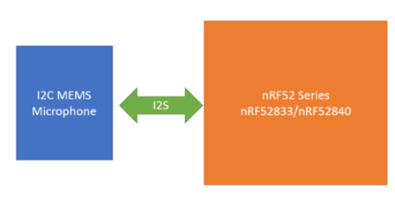
This blog is described how to connect the MEMS Microphone through I2S to Nordic NRF52 Series chipset.
Hardware Requirement:
- NRF52840 DK Board x 1
- Adafruit I2S MEMS Microphone
Adafruit I2S MEMS Microphone
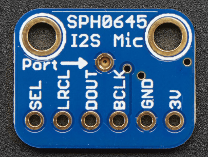
Power Pins
- 3V – this is the power in pin. Technically it can be powered from as low as 1.6V to 3.6V but you’ll need to make sure your logic level matches!
- GND – power and data ground
I2S Data Pins
- BCLK – the bit clock, also known as the data clock or just ‘clock’ – comes from the I2S master to tell the microphone its time to transmit data. This should run at 2-4 MHz but we’ve found you can often run it a little slower and it’ll work fine
- DOUT – the data output from the mic!
- LRCLK – the left/right clock, also known as WS (word select), this tells the mic when to start transmitting. When the LRCLK is low, the left channel will transmit. When LRCLK is high, the right channel will transmit.
- SEL – the channel select pin. By default this pin is low, so that it will transmit on the left channel mono. If you connect this to high logic voltage, the microphone will instantly start transmitting on the right channel.
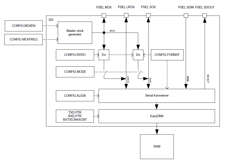
I2S — Inter-IC sound interface
The I2S (Inter-IC Sound) module, supports the original two-channel I2S format, and left or right-aligned formats. It implements EasyDMA for sample transfer directly to and from RAM without CPU intervention.
The I2S peripheral has the following main features:
- Master and Slave mode
- Simultaneous bi-directional (TX and RX) audio streaming
- Original I2S and left- or right-aligned format
- 8, 16 and 24-bit sample width
- Low-jitter Master Clock generator
- Various sample rates
Left right clock (LRCK)
The Left Right Clock (LRCK), often referred to as “word clock”, “sample clock” or “word select” in I2S context, is the clock defining the frames in the serial bit streams sent and received on SDOUT and SDIN, respectively.
In I2S mode, each frame contains one left and right sample pair, with the left sample being transferred during the low half period of LRCK followed by the right sample being transferred during the high period of LRCK.
In Aligned mode, each frame contains one left and right sample pair, with the left sample being transferred during the high half period of LRCK followed by the right sample being transferred during the low period of LRCK.
Consequently, the LRCK frequency is equivalent to the audio sample rate.When operating in Master mode, the LRCK is generated from the MCK, and the frequency of LRCK is then given as:
LRCK = MCK / CONFIG.RATIO
LRCK always toggles around the falling edge of the serial clock SCK.
Serial clock (SCK)
The serial clock (SCK), often referred to as the serial bit clock, pulses once for each data bit being transferred on the serial data lines SDIN and SDOUT.When operating in Master mode the SCK is generated from the MCK, and the frequency of SCK is then given as:
SCK = 2 * LRCK * CONFIG.SWIDTH
The falling edge of the SCK falls on the toggling edge of LRCK.
When operating in Slave mode SCK is provided by the external I2S master.
Master clock (MCK)
The master clock (MCK) is the clock from which LRCK and SCK are derived when operating in Master mode.
The MCK is generated by an internal MCK generator. This generator always needs to be enabled when in Master mode, but the generator can also be enabled when in Slave mode. Enabling the generator when in slave mode can be useful in the case where the external Master is not able to generate its own master clock.
The MCK generator is enabled/disabled in the register CONFIG.MCKEN, and the generator is started or stopped by the START or STOP tasks.
In Master mode the LRCK and the SCK frequencies are closely related, as both are derived from MCK and set indirectly through CONFIG.RATIO and CONFIG.SWIDTH.
When configuring these registers, the user is responsible for fulfilling the following requirements:
- SCK frequency can never exceed the MCK frequency, which can be formulated as:CONFIG.RATIO >= 2 * CONFIG.SWIDTH
- The MCK/LRCK ratio shall be a multiple of 2 * CONFIG.SWIDTH, which can be formulated as:
Integer = (CONFIG.RATIO / (2 * CONFIG.SWIDTH))
The MCK signal can be routed to an output pin (specified in PSEL.MCK) to supply external I2S devices that require the MCK to be supplied from the outside.
When operating in Slave mode, the I2S module does not use the MCK and the MCK generator does not need to be enabled.
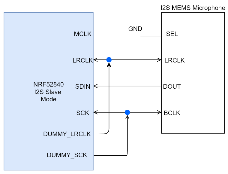
Connection with Adafruit I2S MEMS Microphone
Since the nRF52 series doesn’t support the 24 bits width, it needs to use the 32 bits to act as 24 bits by using external clocks. And then the nRF52 is using the I2S slave mode. More details can be found at
https://github.com/gregtomasch/nRF52_24-bit-_I2S_Microphone_Audio_Recording_Utility
By using the I2S MEMS microphone as the mono audio, the SEL is connected to GND and MCLK is not used if the I2S acts as slave mode.
How to clean up the Windows 10 USB Driver
https://www.uwe-sieber.de/drivetools_e.html#drivecleanup
Reference:
https://www.thewelltemperedcomputer.com/KB/USB.html
Thanks for your interests on my blog. Since 2019, I have created this blog and shared the idea how to do some funny stuffs. I am very pleasure that I get quite a lot of positive feedback. I really hope that this blog helps your own embedded solution development. May I get support from you to keep it in order to maintain the wordpress host service? Your appreciation would be very helpful.
https://jimmywongiot.com/2021/05/26/asking-for-support/


Hi I was wondering if you have tried the above example on your dev board? I tried it on Makerdiary dongle and it did not seem to be working with the Adafruit I2S Mems breakout.
LikeLike
Hi, good topic, although there seems to be a typo in the title. It should be I2S, correct? I ended up here because I thought indeed an I2C mic existed 🙂
LikeLike
Thanks, Rob. You are right.
LikeLike
I dont understand why exactly is MEMs microphone interface available on nrf52 devieces as they do not support BLE audio at all. What are the other applications of it considering with nrf52.
LikeLike
The I2S clock is not exactly matched with the standard. It has some round up. Also, if you need to work on the BLE audio, it should go through the NCS SDK instead of nRF5 SDK.
LikeLike